Hardinge HC Lathe - CNC Conversion
- Skippy1
-
 Topic Author
- Offline
- Senior Member
-

Less
More
- Posts: 44
- Thank you received: 2
27 Apr 2018 09:18 #109697
by Skippy1
Hardinge HC Lathe - CNC Conversion was created by Skippy1
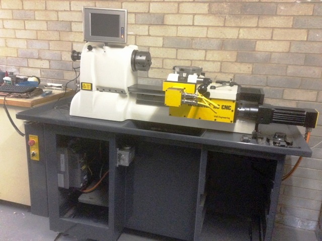
After several years on-and-off, I've finally got the Hardinge lathe operating. I've still got a bit to tidy it up, (find the cabinet doors, etc), but at least it's going.
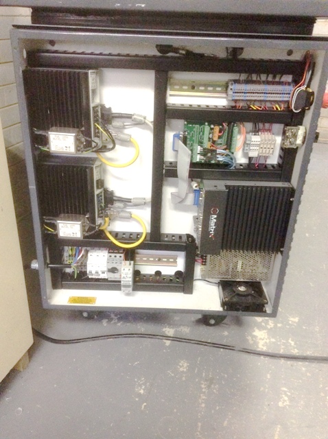
I replaced the original motor, mechanical speed control, switchboard, leadscrews etc, with a 4Kw VFD and motor, Gates GT3 belt drive, Parker servo drives and motors, and NSK and Steinmeyer ground ball screws. I used the common Mesa 5I25/7I76 control option, with a Taiwanese industrial PC running an Atom N270 processor.
I'm a bit intimidated by the servo motor speed and acceleration, and have dialled the values back until I iron the bugs out. PID tuning was , , , , interesting. The emergency stop is wired to kill the: software; the servo drives; and the main spindle drive - just in case.
I can thoroughly recommend the use of slotted plastic cable trunking - it hides a multitude of sins.
Thanks to guys on the forum for their advice and assistance.
Cheers, Steve
Please Log in or Create an account to join the conversation.
- tommylight
-

- Offline
- Moderator
-

Less
More
- Posts: 21722
- Thank you received: 7422
28 Apr 2018 21:43 #109775
by tommylight
Replied by tommylight on topic Hardinge HC Lathe - CNC Conversion
Looks really nice.
Good job.
Good job.
Please Log in or Create an account to join the conversation.
- Skippy1
-
Topic Author
- Offline
- Senior Member
-
Less
More
- Posts: 44
- Thank you received: 2
29 Apr 2018 04:36 #109789
by Skippy1
Replied by Skippy1 on topic Hardinge HC Lathe - CNC Conversion
Thanks Tommy. It's a 10ft paint job - any closer than that, and you see the defects in my spray painting.
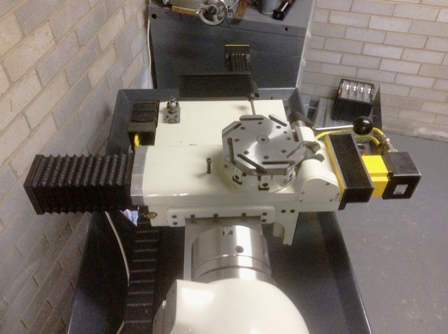
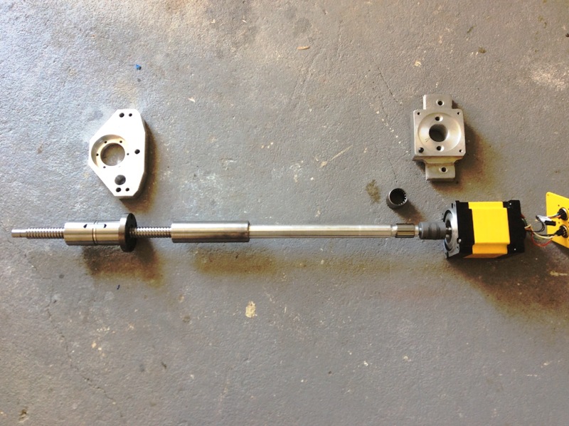
For those who are interested, here is the way I managed in graft the X axis ball screw into the carriage. I tried to bury as much of the new mechanism inside the existing machined passages in the carriage. Overall, it was a bit of a compromise, as the ball screw extends past the back edge of the lathe base, and the motor sticks out the front.
The axial thrust bearing is mounted into an internally stepped and threaded tube, which was eventually loctited into an existing counter bore in the rear of the carriage. The servo motor is mounted on the front of the carriage, and rotates the ball screw using a long drive shaft, which clamps to the ball screw in the cartridge. The motor end of the drive shaft is supported in a needle bearing which was pressed into a newly machined counter-bore the front of the carriage. (This was the only machining I had to do on the carriage, and this was done on a horizontal boring machine after carefully 'clocking up' the front and rear bores.) Only two other parts needed to be manufactured - a motor mount and a ball nut mount. The mount was straightforward, and the nut mount was simply a copy of the original cross feed nut mounting plate, machined to accept the flange of the ball nut.
Basically, a long externally threaded hollow nut holds it all together, and when this, and the motor flexible coupling is removed, the whole assembly, including the drive shaft, can be withdrawn from the rear of the carriage for maintenance etc. It's not an elegant solution, but it's the best I could manage without major modifications to the carriage. I guess I could have mounted a more compact assembly externally on top of the carriage, alongside the cross-slide, but I wanted to get the ball screw aligned with the centre of the cross-slide.
I hope this information helps anyone considering a "HC-CNC Conversion Folly".
Cheers, Steve
Please Log in or Create an account to join the conversation.
- ozzyrob
-

- Visitor
-

29 Apr 2018 05:04 #109790
by ozzyrob
Replied by ozzyrob on topic Hardinge HC Lathe - CNC Conversion
Sweet work
Please Log in or Create an account to join the conversation.
- tommylight
-
- Offline
- Moderator
-
Less
More
- Posts: 21722
- Thank you received: 7422
29 Apr 2018 20:32 #109825
by tommylight
Replied by tommylight on topic Hardinge HC Lathe - CNC Conversion
")
Please Log in or Create an account to join the conversation.
- andypugh
-

- Offline
- Moderator
-
Less
More
- Posts: 19875
- Thank you received: 4642
02 May 2018 22:29 #110062
by andypugh
Personally I like your way.
But why the needle roller? That would be important with a belt drive, but seems superfluous here?
Replied by andypugh on topic Hardinge HC Lathe - CNC Conversion
I guess I could have mounted a more compact assembly externally on top of the carriage, alongside the cross-slide, but I wanted to get the ball screw aligned with the centre of the cross-slide.
Personally I like your way.
But why the needle roller? That would be important with a belt drive, but seems superfluous here?
Please Log in or Create an account to join the conversation.
- Skippy1
-
Topic Author
- Offline
- Senior Member
-
Less
More
- Posts: 44
- Thank you received: 2
04 May 2018 06:16 - 04 May 2018 06:19 #110169
by Skippy1
Replied by Skippy1 on topic Hardinge HC Lathe - CNC Conversion
I agree, if there were a belt or gear drive, there would be significant radial loads on the shaft, requiring a support bearing.
While there is no belt drive, it is a good practice to support long and relatively slender shaft in at least two places to prevent 'whipping' at certain speeds. I was understandably happy with the ball screw end of the shaft - which is rigidly clamped to the ball screw , and well supported by the angular contact bearing. I was uncertain if the flexible coupling at the motor end, by itself, would provide sufficient support. Also, flexible coupling are known to produce side loads on shafts, the size of which is dependant upon the type of coupling, and the axial misalignment of the two shafts. While these loads are significantly less that those from belt drives, they are a factor.
Anyway, while I may have got away without a bearing, there were a few known unknowns, and I thought it prudent to fit a bearing to the motor end of the shaft - just to be sure.
Cheers, Steve.
Last edit: 04 May 2018 06:19 by Skippy1. Reason: grammer
Please Log in or Create an account to join the conversation.
- andypugh
-
- Offline
- Moderator
-
Less
More
- Posts: 19875
- Thank you received: 4642
04 May 2018 09:21 #110183
by andypugh
Good point, I had missed the presence of the flex coupling.
With that length of shaft you could probably have not used a flexible coupling at all from a radial perspective, but there would still need to be some allowance for axial shift if the motor bearings and ballscrew bearings are to avoid "fighting" each other.
I have nearly always used a belt (or inverted-tooth chain) on my drives so I am not really up to speed on direct drives.
Replied by andypugh on topic Hardinge HC Lathe - CNC Conversion
I was uncertain if the flexible coupling at the motor end, by itself, would provide sufficient support.
Good point, I had missed the presence of the flex coupling.
With that length of shaft you could probably have not used a flexible coupling at all from a radial perspective, but there would still need to be some allowance for axial shift if the motor bearings and ballscrew bearings are to avoid "fighting" each other.
I have nearly always used a belt (or inverted-tooth chain) on my drives so I am not really up to speed on direct drives.
Please Log in or Create an account to join the conversation.
- mclausen
- Offline
- Senior Member
-
Less
More
- Posts: 43
- Thank you received: 1
05 Nov 2018 20:28 - 05 Nov 2018 20:30 #120033
by mclausen
Replied by mclausen on topic Hardinge HC Lathe - CNC Conversion
Clean build! I also did a Hardinge retrofit, but I started with one that already had a Bandit CNC.
What GUI are you using?
It looks like you are using the manual lever for tool changes. Mine already had a rotary air cylinder that replaced the lever. I wrote a custom component to operate the tool changer if you are interested.
What GUI are you using?
It looks like you are using the manual lever for tool changes. Mine already had a rotary air cylinder that replaced the lever. I wrote a custom component to operate the tool changer if you are interested.
Last edit: 05 Nov 2018 20:30 by mclausen.
Please Log in or Create an account to join the conversation.
- Skippy1
-
Topic Author
- Offline
- Senior Member
-
Less
More
- Posts: 44
- Thank you received: 2
06 Nov 2018 05:30 #120075
by Skippy1
Replied by Skippy1 on topic Hardinge HC Lathe - CNC Conversion
I'm currently using the standard Axis GUI.
Yes, manual tool change for now. Sometime in the future I would like to convert the tool turret to CNC control. I have already got a small Parker geared servo motor, which I think may be suitable for operating the indexer.
Cheers, Steve
Yes, manual tool change for now. Sometime in the future I would like to convert the tool turret to CNC control. I have already got a small Parker geared servo motor, which I think may be suitable for operating the indexer.
Cheers, Steve
Please Log in or Create an account to join the conversation.
Time to create page: 0.430 seconds