Prototrak Plus Retrofit with Mesa 7i77 & 5i25 cards
- Todd Zuercher
-

- Online
- Platinum Member
-

Less
More
- Posts: 4963
- Thank you received: 1369
10 Mar 2017 19:57 - 10 Mar 2017 19:59 #89372
by Todd Zuercher
Replied by Todd Zuercher on topic Prototrak Plus Retrofit with Mesa 7i77 & 5i25 cards
You are trying to find out what the output of your DC power supply (not the transformer).
For example, you should connect your light between the terminals the brown and white wires that connected to the old servo amp, Then with your meter measure the voltage between those same terminals (with the light on however dim it may be).
For example, you should connect your light between the terminals the brown and white wires that connected to the old servo amp, Then with your meter measure the voltage between those same terminals (with the light on however dim it may be).
Last edit: 10 Mar 2017 19:59 by Todd Zuercher.
The following user(s) said Thank You: new2linux
Please Log in or Create an account to join the conversation.
10 Mar 2017 20:21 - 11 Mar 2017 03:26 #89374
by new2linux
Replied by new2linux on topic Prototrak Plus Retrofit with Mesa 7i77 & 5i25 cards
Andy thanks for hanging in there with me!! You are a true gentleman all the way thru!!
This is how it should of been done, looking at the end of PCB (only did one side "x") referencing earlier pic of diagram:
40v = W & BR; 40V = BL & BR; 75V = W & BR (W=WHITE; BR=BROWN; BL=BLUE; the original color leads)
A 110v light bulb was jumper-ed to the leads in question, voltmeter applied to get reading.
Many,many thanks!
Edit:am I correct that the white goes to pin 5; brown and black (on pin 3 or pin 4) don't mater as much as long as the drive (rotation) matches the encoder and both amplifiers are the same.
Last edit: 11 Mar 2017 03:26 by new2linux. Reason: just a guess
Please Log in or Create an account to join the conversation.

11 Mar 2017 00:25 #89387
by andypugh
Replied by andypugh on topic Prototrak Plus Retrofit with Mesa 7i77 & 5i25 cards
I am confused by BL=Blue and BL=Black.
Can you try to figure out the wiring inside the PCB on the capacitor? I am a bit puzzled by the extra wire which bypasses the rectifier. It could be a centre-tap on the transformer, doing something clever that I don't understand.
Do you know the voltage rating of the original drives? Or the motors?
Can you try to figure out the wiring inside the PCB on the capacitor? I am a bit puzzled by the extra wire which bypasses the rectifier. It could be a centre-tap on the transformer, doing something clever that I don't understand.
Do you know the voltage rating of the original drives? Or the motors?
The following user(s) said Thank You: new2linux
Please Log in or Create an account to join the conversation.
11 Mar 2017 03:29 #89400
by new2linux
Replied by new2linux on topic Prototrak Plus Retrofit with Mesa 7i77 & 5i25 cards
andy, thank you! my apologies, there was no black leads, just brown ones. I will get the PCB out and study how it is routed, maybe take a pic if it will help.
thanks to you!!
thanks to you!!
Please Log in or Create an account to join the conversation.
11 Mar 2017 13:36 - 12 Mar 2017 14:54 #89414
by new2linux
Replied by new2linux on topic Prototrak Plus Retrofit with Mesa 7i77 & 5i25 cards
Many thanks for all the help!
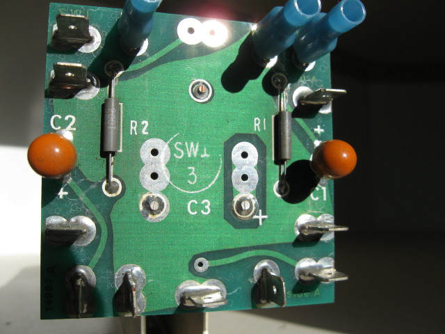
Attached are a few pic of the cap/PCB, labeled top (viewed from back), labeled side (viewed from back), as you will see the blue "crimp on" and the orange small capacitor are in the pic for ref. The front I tried to get the light to help with the circuit
 id.
id.
If I can assist with a voltmeter to test continuity please advise. Take note this assembly is not the one in use, there are 2 of these.
many thanks! helpful comments are warmly welcomed!
edit: The terminals in question (looking at front.jpg) are on right side just under the light blue "crimp on", there is a terminal that is in the horizontal position (unlike the light blue "crimp on" that is vertical), then a capacitor, then 2 terminals that are in the horizontal position. It is these that are as per a prior post labeled by color, but if we now look at it as 1 at the top,2 mid and 3 bottom the following values were results of test.
40v=2 & 3; 40v=1 & 3; 75v=2 & 1
I include this here to keep track.
Edit: The diagram is my best effort (please comment if necessary) to get this documented for others. The top "left open" there is no component there, as seen in pic to the left (I hope). Note 3 the pin of the capacitor (c3) does not seem to go anywhere. The list of components are to the left, this is what was marked on the components, open to suggestions. The dotted lines I am not completely shore, tested good continuity, but could not verify visually, if that is where they go 100%. The notes may not read so well: Note 1 PCB has large copper foot print (on far-side) goes to the + side of rectifier; Note 2 PCB has large copper foot print (on near-side) goes to the - side of rectifier. Lower left terminal on PCB goes to #1 on transformer.
Attached are a few pic of the cap/PCB, labeled top (viewed from back), labeled side (viewed from back), as you will see the blue "crimp on" and the orange small capacitor are in the pic for ref. The front I tried to get the light to help with the circuit
If I can assist with a voltmeter to test continuity please advise. Take note this assembly is not the one in use, there are 2 of these.
many thanks! helpful comments are warmly welcomed!
edit: The terminals in question (looking at front.jpg) are on right side just under the light blue "crimp on", there is a terminal that is in the horizontal position (unlike the light blue "crimp on" that is vertical), then a capacitor, then 2 terminals that are in the horizontal position. It is these that are as per a prior post labeled by color, but if we now look at it as 1 at the top,2 mid and 3 bottom the following values were results of test.
40v=2 & 3; 40v=1 & 3; 75v=2 & 1
I include this here to keep track.
Edit: The diagram is my best effort (please comment if necessary) to get this documented for others. The top "left open" there is no component there, as seen in pic to the left (I hope). Note 3 the pin of the capacitor (c3) does not seem to go anywhere. The list of components are to the left, this is what was marked on the components, open to suggestions. The dotted lines I am not completely shore, tested good continuity, but could not verify visually, if that is where they go 100%. The notes may not read so well: Note 1 PCB has large copper foot print (on far-side) goes to the + side of rectifier; Note 2 PCB has large copper foot print (on near-side) goes to the - side of rectifier. Lower left terminal on PCB goes to #1 on transformer.
Last edit: 12 Mar 2017 14:54 by new2linux. Reason: additional info; add diagram (this may not be perfict)
Please Log in or Create an account to join the conversation.
11 Mar 2017 16:13 - 12 Mar 2017 15:13 #89423
by new2linux
Replied by new2linux on topic Prototrak Plus Retrofit with Mesa 7i77 & 5i25 cards
Many thanks to all that make this possible!!
Am I correct that the leads in question are described here? www.a-m-c.com/wp-content/uploads/support...ual_Analog_Panel.pdf
This is page 37 (3.13 Potentiometer input); if so, the leads should read as 3 position on PCB goes to 5 on (P2); and 2 position on PCB goes to 4 on (P2); and 1 position on PCB goes to 3 on (P2).
Wondering if my thinking is sound? I have reread the full manual again and see more work ahead.
Just need 2nd opinion.
thanks!
Edit: I am at the "Current Limiting Procedure 4.1.6" in the Initial setup part of manual, and there is some information about the servos that I am not shore of. Specifically: Need "current requirement" of servo; Need "continuous current requirement" of servo; Need "continuous current limit" requirement of servo; Need "peak current" requirement; Need "peak current limit" requirement. This is used to set DIP switches and potentiometer before any "Drive set up can be started".
Many thanks for any suggestions would be warmly welcomed!!
Last edit: 12 Mar 2017 15:13 by new2linux.
Please Log in or Create an account to join the conversation.
13 Mar 2017 13:09 #89513
by andypugh
Replied by andypugh on topic Prototrak Plus Retrofit with Mesa 7i77 & 5i25 cards
I remain confused. Your schematic shows nothing connected to C3+
The following user(s) said Thank You: new2linux
Please Log in or Create an account to join the conversation.
13 Mar 2017 14:04 - 13 Mar 2017 14:09 #89518
by new2linux
Replied by new2linux on topic Prototrak Plus Retrofit with Mesa 7i77 & 5i25 cards
andypugh, thanks you!! The if you read note 1 is connected to all the places you see note 1, so that would the top terminal on the right side, the very bottom on the left side, along the top it is the to the left most along the top (I cut the pic off, but the diagram lead goes all the way to the right, then to the bottom, then the pic has it back). This PCB is symmetrical except the very top, (the pic has note "left open"), I don't know if a capacitor like c1 or c2 would make it possible to use that as "z" axes power supply to amplifier.
Many thanks!!
edit:this is part of earlier post:The dotted lines I am not completely shore, tested good continuity, but could not verify visually, if that is where they go 100%. The notes may not read so well: Note 1 PCB has large copper foot print (on far-side) goes to the + side of rectifier; Note 2 PCB has large copper foot print (on near-side) goes to the - side of rectifier. Lower left terminal on PCB goes to #1 on transformer.
Last edit: 13 Mar 2017 14:09 by new2linux. Reason: clearify
Please Log in or Create an account to join the conversation.

13 Mar 2017 18:30 #89540
by lakeweb
Replied by lakeweb on topic Prototrak Plus Retrofit with Mesa 7i77 & 5i25 cards
Hi new2,
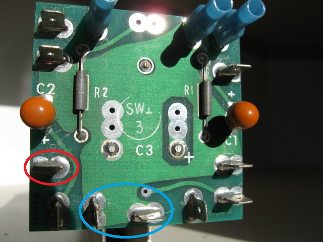
I would recommend you get a friend that has electrical experience look in on you. But for now, the best I can make of your diagram says:
The red circle is your motor power supply positive and the blue the negative. And goes to what is called 'High voltage' from the PDF: servosystems.com/pdf/amc/12a8.pdf that Andy had offered you, is where this gets connected. The other PDF is not retentive for this. And that is all you will use from that power supply.
You will need 5 volts for the 7i77. I've not looked into it, but you may be able to jump that from the 5i25. Or you can buy:
Power Supply or the type that Andy previously offered.
And then if you need to use the field contacts to drive relays from the 7i77, that is potentially yet another power supply. Typically 24 volts.
On my mill there are five different power sources. I get the feeling you think just the one supply will do. Is that the case?
Best, Dan.
The following user(s) said Thank You: new2linux
Please Log in or Create an account to join the conversation.
13 Mar 2017 18:49 #89541
by andypugh
I actually think that left, right and top are where the moor drives connect (with a set of crimps supplied for connecting a third axis)
I believe that the rectified voltage feeds in at the bottom. Either of the two in the blue circle can be negative from the rectifier.
But: I don't know what the extra wire from the transformer to that board bypassing the retifier is for, neither do I know what the extra terminals are for which seem to be coupled via the small capacitors.
It is quite likely that you can ignore those with your new drives.
But, I echo the sentiment that having someone who knows one end of a multimeter from the other give it a check-over would be a good idea.
Replied by andypugh on topic Prototrak Plus Retrofit with Mesa 7i77 & 5i25 cards
The red circle is your motor power supply positive and the blue the negative. And goes to what is called 'High voltage' from the PDF: .
I actually think that left, right and top are where the moor drives connect (with a set of crimps supplied for connecting a third axis)
I believe that the rectified voltage feeds in at the bottom. Either of the two in the blue circle can be negative from the rectifier.
But: I don't know what the extra wire from the transformer to that board bypassing the retifier is for, neither do I know what the extra terminals are for which seem to be coupled via the small capacitors.
It is quite likely that you can ignore those with your new drives.
But, I echo the sentiment that having someone who knows one end of a multimeter from the other give it a check-over would be a good idea.
The following user(s) said Thank You: new2linux
Please Log in or Create an account to join the conversation.
Moderators: piasdom
Time to create page: 0.155 seconds