mesa 5i25 and mx4660 installation and configuration
- andypugh
-

- Offline
- Moderator
-

Less
More
- Posts: 19861
- Thank you received: 4636
07 Jun 2017 16:17 #94246
by andypugh
I guess you are using the parallel port?
You could try finding a parallel port with a different behaviour. Some are hardware-inverted, for example, and might not have the problem.
The "correct" answer is to use a charge-pump circuit. (LinuxCNC has a suitable HAL module)
wiki.linuxcnc.org/cgi-bin/wiki.pl?About_Charge_Pumps
Replied by andypugh on topic mesa 5i25 and mx4660 installation and configuration
We wired the motors and 1 of the 4 proximity switches. The problem is now, that I want to have the cleaner, the vacuum pump and the spindle controlled by relays. But when I turn on the Linuxcnc Computer first, it sends a high signal to the Output connection, that means, the relays stay tuned until I start Linuxcnc itself. Have you got any idea how to keep the signal low?
I guess you are using the parallel port?
You could try finding a parallel port with a different behaviour. Some are hardware-inverted, for example, and might not have the problem.
The "correct" answer is to use a charge-pump circuit. (LinuxCNC has a suitable HAL module)
wiki.linuxcnc.org/cgi-bin/wiki.pl?About_Charge_Pumps
Please Log in or Create an account to join the conversation.
- goofy
- Offline
- Junior Member
-

Less
More
- Posts: 20
- Thank you received: 1
07 Jun 2017 16:25 #94249
by goofy
Replied by goofy on topic mesa 5i25 and mx4660 installation and configuration
my setup is a mesa 5i25 and I want to use both ports (P2, P3). I dont know if thats a parport?! Is there any possibility to rewrite the bitfile to invert the Output pins?
I dont know anything about the ChargePump. I just set the jumper at the mx4660 to on and thats it...
I dont know anything about the ChargePump. I just set the jumper at the mx4660 to on and thats it...
Please Log in or Create an account to join the conversation.
- PCW
-

- Offline
- Moderator
-
Less
More
- Posts: 17917
- Thank you received: 5246
07 Jun 2017 16:42 #94251
by PCW
Replied by PCW on topic mesa 5i25 and mx4660 installation and configuration
The 5I25 cannot easily have low outputs at startup,
(all GPIO pins have pullup resistors and are inputs at startup)
Many CNC BOBs use a chargepump circuit to disable outputs
until the controller signals that its running via the chargepump signal
since parallel port outputs do not have a defined startup state due to
BIOS and OS hardware probing at startup
The MX4660 has a chargepump circuit but unfortunately its rather useless
since it does not disable the outputs, only the step drives and it doesn't have a
chargepump status output that could be used as an output enable
Please Log in or Create an account to join the conversation.
- goofy
- Offline
- Junior Member
-
Less
More
- Posts: 20
- Thank you received: 1
07 Jun 2017 17:20 - 07 Jun 2017 17:26 #94252
by goofy
Replied by goofy on topic mesa 5i25 and mx4660 installation and configuration
Thanks a lot for your explanations! Know I start to understand the ChargePump circuit. Its really a pity...
But anyway, we can teach ourselves to start first Linuxcnc and than turn on the hardware.
I will connect the remaining switches and the next days Im going to complete the machine itself. For sure I will come up with more questions. I hope you are not annoyed yet?!
Thanks
Mathias
But anyway, we can teach ourselves to start first Linuxcnc and than turn on the hardware.
I will connect the remaining switches and the next days Im going to complete the machine itself. For sure I will come up with more questions. I hope you are not annoyed yet?!
Thanks
Mathias
Last edit: 07 Jun 2017 17:26 by goofy.
Please Log in or Create an account to join the conversation.
- goofy
- Offline
- Junior Member
-
Less
More
- Posts: 20
- Thank you received: 1
08 Jul 2017 10:12 #95499
by goofy
Replied by goofy on topic mesa 5i25 and mx4660 installation and configuration
Hi,
Im back again with some questions. We assembled the Y and X axis and tried to run the first time the machine to measure the work area. There is the first problem: It moves, but very very slow. Could you give me an advise how to get the desired jogging speed of at least 10m/min? In the next days I want to touch the configuration of 3 Axis and 4 joints for the Y. If anyone has a configuration to have a look at, It would be great.
Thanks a lot
Mathias
P.S. attached some pictures of the machine itself...
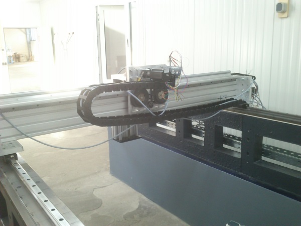
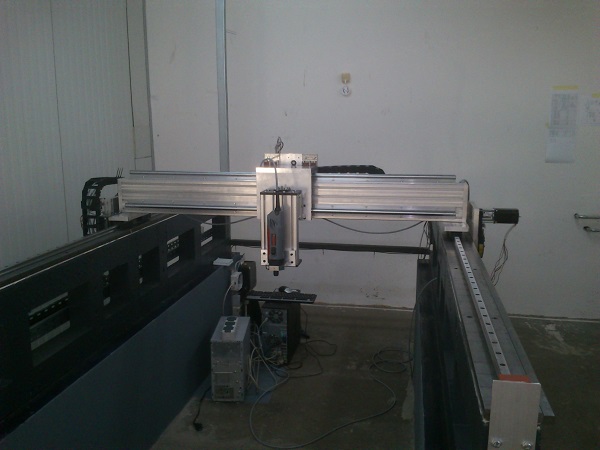
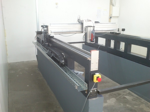
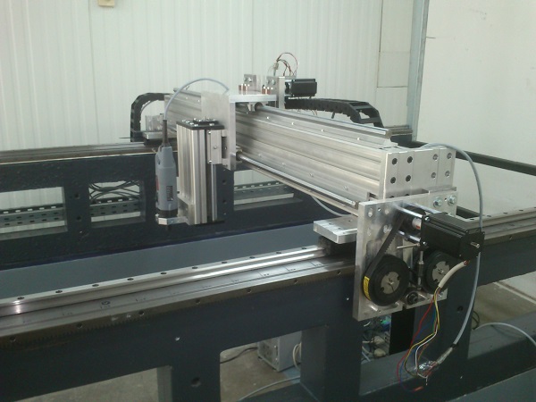
Please Log in or Create an account to join the conversation.
- tommylight
-

- Away
- Moderator
-
Less
More
- Posts: 21630
- Thank you received: 7385
08 Jul 2017 12:34 #95501
by tommylight
Replied by tommylight on topic mesa 5i25 and mx4660 installation and configuration
Open the .ini file with a text editor ( gedit or mousepad or nano ) and look for max_velocity and max_acceleration, edit them as you need for each axis ( not before finding the right ratio or scale ), save, reload Linuxcnc and test.
Set the scale first.
Set the scale first.
Please Log in or Create an account to join the conversation.
- goofy
- Offline
- Junior Member
-
Less
More
- Posts: 20
- Thank you received: 1
08 Jul 2017 13:48 #95502
by goofy
Replied by goofy on topic mesa 5i25 and mx4660 installation and configuration
Thanks for your answer.
When I open up the .ini file, there are a lot of VELOCITIES...
The first one is in the DISPLAY area. At the moment at 16.666667. The documentation says something about machine units? Is it in mm, s or rpm? The next velocities are in the joints sections. The values are MAX_VELOCITY = 500.0 and MAX_ACCELERATION = 800.0. At the moment its for all three axis the same, but only X and Y have the same hardware. They have both a rack and pinion drive.
The calculation is: pi x 2mm (modul 2) x 12 (number of teeth) x 0,53125 (gear with 34 and 64 teeth) = 40,0553 mm per revolution. At the moment I have the switches for the microstepping set to 1/10. Thats 2000 steps per revolution and 0,02 mm per step. The Scale I use at the moment is therefor 1/0,02 = 49,93 steps per mm. Is that right?
Thanks a lot and regards
Mathias
Please Log in or Create an account to join the conversation.
- rodw
-

- Offline
- Platinum Member
-

Less
More
- Posts: 11950
- Thank you received: 4068
08 Jul 2017 20:43 #95515
by rodw
Replied by rodw on topic mesa 5i25 and mx4660 installation and configuration
Your calculations look right to me
The jog speed is set by DEFAULT_LINEAR_VELOCITY in the ini file
See
forum.linuxcnc.org/49-basic-configuratio...ge-default-jog-speed
Assuming you have set the default units to be metric, all of the velocities are in machine units per second so 10 m/min gives 10000/60 mm/sec = 166.66667
I think you are running at 100 mm/min (16.66667)
Please Log in or Create an account to join the conversation.
- goofy
- Offline
- Junior Member
-
Less
More
- Posts: 20
- Thank you received: 1
17 Jul 2017 16:00 #95912
by goofy
Replied by goofy on topic mesa 5i25 and mx4660 installation and configuration
Hi,
thanks for your answer! Meanwhile I got the machine running at reasonable speed of 10m/min.
With the great help of IchGucksLive in the linuxcnc chat, the home switches are configured, the soft limits are set and many of my questions were answered. At the moment I hardly try to understand the structure of the hal. I have a router (Kress) on a relay and want to connect it to spindle on/off (M4/M5). The same I want to do with the vacuum table and the dust collection. The pins in the hal file are
#setp hm2_5i25.0.gpio.029.is_output true
#net spindel hm2_5i25.0.gpio.029.out
#setp hm2_5i25.0.gpio.024.is_output true
#net vakuum hm2_5i25.0.gpio.024.out
#setp hm2_5i25.0.gpio.017.is_output true
#net absauge hm2_5i25.0.gpio.017.out
If you have any idea to connect these pins to M4/M5, M8/M9, It would be great.
Thanks a lot and regards
Mathias
Please Log in or Create an account to join the conversation.
- Todd Zuercher
-

- Away
- Platinum Member
-
Less
More
- Posts: 4742
- Thank you received: 1454
17 Jul 2017 16:47 - 17 Jul 2017 16:53 #95924
by Todd Zuercher
Replied by Todd Zuercher on topic mesa 5i25 and mx4660 installation and configuration
For your spindle controls in your hal file M3 will trigger the signal "spindle-cw" (to start the spindle in the normal forward or clockwise direction), and M4 will trigger the signal "spindle-ccw" (for reverse). M5 will change both those signals to false (as well as the spindle-enable).
To connect one of those singals to the halpin hm2_5i25.0.gpio.029.out by adding a line like this to your hal file.
For connecting to the coolant mist/flood (M7/M8) your hal file has signals called "coolant-mist" and "coolant-flood" and like above you could add this to your hal file.This would turn on the pin "hm2_5i25.0.gpio.024.out" with the M7 g-code, and turn on "hm2_5i25.0.gpio.017.out" with the M8 g-code and turn them both off with an M9.
There is no way to separate the action of the M7/M8 commands they will always both be shut off by M9.
For this reason for the vacuum table and dust collection controls on the routers I've configured. I choose to use a custom M-codes (M1xx) to control them.
linuxcnc.org/docs/html/gcode/m-code.html#mcode:m100-m199
Here is what the file I use for turning on my vacuum looks like (using your output pin).
M111 (vacuum on)M112 (vacuum off)
To connect one of those singals to the halpin hm2_5i25.0.gpio.029.out by adding a line like this to your hal file.
net spindle-cw => hm2_5i25.0.gpio.029.outFor connecting to the coolant mist/flood (M7/M8) your hal file has signals called "coolant-mist" and "coolant-flood" and like above you could add this to your hal file.
net coolant-mist => hm2_5i25.0.gpio.024.out
net coolant-flood => hm2_5i25.0.gpio.017.outThere is no way to separate the action of the M7/M8 commands they will always both be shut off by M9.
For this reason for the vacuum table and dust collection controls on the routers I've configured. I choose to use a custom M-codes (M1xx) to control them.
linuxcnc.org/docs/html/gcode/m-code.html#mcode:m100-m199
Here is what the file I use for turning on my vacuum looks like (using your output pin).
M111 (vacuum on)
M111
#!/bin/bash
# file to turn on  hm2_5i25.0.gpio.024.out to turn on Vacuum
halcmd setp  hm2_5i25.0.gpio.024.out 1
exit 0
M112
#!/bin/bash
# file to turn off hm2_5i25.0.gpio.024.out to turn off Vacuum
halcmd setp hm2_5i25.0.gpio.024.out 0
exit 0
Last edit: 17 Jul 2017 16:53 by Todd Zuercher.
Please Log in or Create an account to join the conversation.
Time to create page: 0.247 seconds