Figuring out what kind of move is being executed?
- DaBit
- Offline
- Elite Member
-

- Posts: 203
- Thank you received: 19


The receiver outputs the trigger signal, but also a 'probe ready' signal. This signal is activated when the probe electronics think everything is OK and the communication link is up and running.
Currently I combine these signals so motion.probe-input is active when the probe is not ready. If something fails (battery empty, comm link down, contact failure, etc) at least I get the 'probe already active before start of probe move' message.
that triggers.
Of course this breaks non-probe moves when there is no probe, so I use one of the motion.digital-output signals to enable the probe before a move and disable it afterwards.
That works, but it would be nicer if there were HAL-pins available that indicated what kind of move (G1/2/3, G0, G38.x, etc.) is currently being executed. Then I could activate the probe signal automagically when the interpreter executes a G38.x..
Is that possible, or do I have to resort to remapping G38.x?
Please Log in or Create an account to join the conversation.
- BigJohnT
-

- Offline
- Administrator
-

- Posts: 3990
- Thank you received: 994
The currently active G codes can be read by linuxcnc stat using the python interface.
linuxcnc.org/docs/html/config/python-int...xcnc_stat_attributes
JT
Please Log in or Create an account to join the conversation.
- REEEN
- Offline
- Senior Member
-

- Posts: 66
- Thank you received: 1
motion.motion-type OUT S32
These values are from src/emc/nml_intf/motion_types.h
1: Traverse
2: Linear feed
3: Arc feed
4: Tool change
5: Probing
6: Rotary axis indexing
Greets Rene
Please Log in or Create an account to join the conversation.
- cncbasher
- Offline
- Moderator
-

- Posts: 1021
- Thank you received: 202
as well as making the probe switch on / off through ir and battery ok etc
let me know what you need by mail if you wish , and i'll see what i can come up with
do you need to add to the protocol etc or just pins ,
i'm going to try the simple comp way first and see if that gives me everything
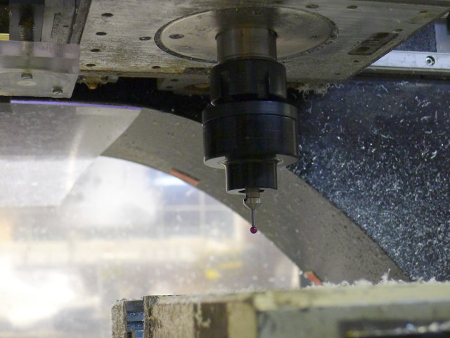
nice probe too ! ,
Please Log in or Create an account to join the conversation.
- DaBit
- Offline
- Elite Member
-
- Posts: 203
- Thank you received: 19
Very nice work! I wish I had a probe...
The currently active G codes can be read by linuxcnc stat using the python interface.
Little things like a toolsetter switch and a 3D probe make life sooo much easier. Without those a lot of time is spent on setting up.
I still have to dive into the Python interface. Somehow Python and I do not like each other.
This is what you need:
motion.motion-type OUT S32
Exactly what I want! I wonder how I could have browsed through the motion.xxx pins and still have missed that one!
i'm in the middle of doing exacty that , as i,m making a probe ir reciever , and interfacing to Hal etc
as well as making the probe switch on / off through ir and battery ok etc
let me know what you need by mail if you wish , and i'll see what i can come up with
do you need to add to the protocol etc or just pins ,
Currently I do not need much. The interface with LinuxCNC is simply 2 digital wires, giving me 4 possible states. Just enough to indicate:
- Probe not ready, cause unknown
- Probe not ready, battery low
- Probe ready, no trigger
- Probe ready, trigger
Which is sufficient. And 2 digital wires make it easy to bring the probe status into HAL.
What I basically need is:
- The ability to throw an error when a probe move is started when the probe is not ready.
- The ability to gate the probe trigger signal until we are in a real probing move.
Both can be accomplished using motion.motion-type and standard HAL logic.
BTW: the best method would be 'real' communication, synchronised timestamp counters running both inside the RT environment and probe, and having the probe report the timestamp at which a change of state occurred.
That way you get rid of the communication and servo thread latencies once and for all.
(say you are running the servo thread at 1kHz and you are probing at 500mm/min, which is actually quite slow. Then the uncertainity of the trigger point due to sampling the probe signal at 1kHz is already 4um...
i'm going to try the simple comp way first and see if that gives me everything
I am contemplating 2 components and a NGC program too for performing this:
- NGC program probes the table and a calibrated ring such as a ball bearing from the center in a number of vectors going 360 degrees round and dumps the deviations of actual vs expected (=ring radius) vector length to a file. By doing it like this I have more calibration values than only -X.+X,-Y, +Y, -Z angles.
- At LinuxCNC start a userspace component reads the file contents and dumps it in shared memory.
- During a probe move an RT component calculates the motion vector, looks up the correction value, corrects for half the servothread delay and communication delay, and spits out a correction value.
- Either a remapped G38.x or the probing subroutines themselves use this value to correct the G38.x result.
This way nonlinearities and deviations in the probe are corrected, and there is no need anymore to exactly center the probe tip.
Are your plans comparable to this?
Please Log in or Create an account to join the conversation.
- cncbasher
- Offline
- Moderator
-
- Posts: 1021
- Thank you received: 202
i cant see first hand how your idea of using a ball bearing for example will calibrate a probe , as with any probe it can be placed in a toolholder in any position
i can see it working if you can hold the spindle in the same place everytime and it not rotate , and insert the probe in the same axial postion .
but i think this is over complicating ...
i have a data stream over the ir path , with battery condition and on off states ,
i have 2 ideas to interogate this 38Khz stream data , and collate the points etc ,
and using Mcodes to start & stop and switch on the probe once it's inserted into the spindle , as mine is used in a toolchanger , the mcode could pick the pocket and turn on the probe
and then use the data etc .
time for thoughts & plan ideas , i,m not convinced to use g38.x , at least to start with . g38 is used for probe-in at present , but i have not looked at it's limitations
Please Log in or Create an account to join the conversation.
- DaBit
- Offline
- Elite Member
-
- Posts: 203
- Thank you received: 19
have you seen Probe_screen ?
Yes, but I still have to play with it. Currently I am still using something I already had before verser made probe_screen.
i cant see first hand how your idea of using a ball bearing for example will calibrate a probe , as with any probe it can be placed in a toolholder in any position
i can see it working if you can hold the spindle in the same place everytime and it not rotate , and insert the probe in the same axial postion .
That's exactly what I want. Radial position is easily constrained with a simple feeler pin that hits a feature on the head. Axial posiition is less easy since my spindle uses an ER25 nose. But a collet that is ground down so it only touches the cone inside the spindle at three locations op top and three on bottom is reasonably repeatable. Besides that I normally do not require ultra precision on the Z-axis trigger point and if I do I can always touch down on the table.
But I think I am going to move it outside the spindle nose; it is taking up too much of my Z-travel this way. So I will change the mounting to a 3-balls, 3-Vgrooves and a magnet system. I use the same for my USB camera (click) that that repeats to well withing the accuracies of my 0.01mm DTI's.
Would make placing the probe, doing the measurements/zero setting/etc, remove the probe, and go milling a lot easier too.
but i think this is over complicating ...
I don't think so. I made a probe before, but centering the tip to reasonable accuracy is quite frustrating. And keeping that tip centered is another thing.
Besides that all 6-balls-3-rods based probes suffer from lobing because the force required to trip the measurement varies in the circle and things are not infinitely stiff. Which is one of the reasons why I use hardened steel balls/rods and anodised aluminium for the housing and inner parts instead of plastic.
BTW: the electronics does contact resistance measurements and shuts off the current to the contacts as soon as it senses an increase or decrease so that the actual breaking/making occurs without current flow. And thus without micro-erosion of the contacts. If you leave the current on, you basically made an EDM machine chewing away the contacts.
I also intended to fill the contact area with some inert fluid, but so far I have not found anything that works decently. All liquids I tried cause loss of contact problems at very light triggers.
Current contact-area fill is argon, and that works well. But I have no illusions; the argon will diffuse through the NBR70 seals sooner or later.
If the probe calibration is a simple and mostly automatic process and the probe has a fixed orientation compared to the spindle, it is a better solution IMHO. No more tedious centering, lobing is corrected, and it is very easy to construct a probe tip using a hardened steel ball glued onto a piece of carbide rod. Saves money; sooner or later 'oops' happens and the probe tip breaks.
When constructing probe tips this way, the ball is not centered within microns of course. With calibration/correction, that does not matter.
i have a data stream over the ir path , with battery condition and on off states ,
I am using standard IrDA SIR at 115200 baud using a single byte to signal state and extra error correction bits. A fairly slow method to communicate; it gives me a 91 usec latency between trigger detect and output of receiver changing state. But that latency is fixed, and therefore can be corrected when needed. Although synchronized timestamping clocks at both ends would be nicer.
and using Mcodes to start & stop and switch on the probe once it's inserted into the spindle , as mine is used in a toolchanger ,
Aaah, the luxury of a toolchanger
")
My probe is activated/woken up from standby by triggering the probe itself. Makes sense in my situation, just tap the probe tip once while manually mouting the probe. Happens 'by accident' anyway. And even if LinuxCNC would not react to 'probe ready' the wakeup is fast enough (several 10's of microseconds) to stop the probe before damage occurs.
It goes back to sleep when the communication link with the receiver is broken.
To be really sure I have to deplete a battery first, but calculations show that the CR2032 cell should last several hundred hours of probing (0,6mA average current draw) and many years of standby.(~1uA of current draw).
g38 is used for probe-in at present , but i have not looked at it's limitations
My only issue is that there is only one G38 and only one motion.probe-in. When using more than one probe (toolsetter, touch probe, etc..) one has to OR those signals together, guess which device caused the trigger and if one device breaks the others are instantly not useable anymore without some HAL hacking.
Also the fact that it runs at the servo thread also causes a fairly large uncertainity in the probed position at higher probing speeds. Not so important on my hobby machine, but to be able to use the repeatability of a 'real' probe such as made by Renishaw & co you have to keep the probing speed very low. But I am sure that a bit of Mesa FPGA here and a remap there can solve all that when needed.
When interested (video isn't that interesting really): probe testing using slightly modified smartprobe.ngc from the examples:
Please Log in or Create an account to join the conversation.
- andypugh
-

- Offline
- Moderator
-
- Posts: 19875
- Thank you received: 4642
Also the fact that it runs at the servo thread also causes a fairly large uncertainity in the probed position at higher probing speeds. Not so important on my hobby machine, but to be able to use the repeatability of a 'real' probe such as made by Renishaw & co you have to keep the probing speed very low.
One solution is to make a fast probe move until the probe breaks contact, then make a slow probe move in the reverse direction until the probe makes contact.
Time-stamping the probe event might not help much. You find out when the event happened but you really care about where it happened, and the encoder counts only get converted to position in the servo thread
There is _something_ mysterious and undocumented in the Mesa encoder related to latched counts, it might be possible to use that.
Docs: www.linuxcnc.org/docs/html/man/man9/hostmot2.9.html#encoder
Actual pins created in code: git.linuxcnc.org/gitweb?p=linuxcnc.git;a...563943d;hb=HEAD#l461
And a mention of "LATCH_ON_PROBE" git.linuxcnc.org/gitweb?p=linuxcnc.git;a...563943d;hb=HEAD#l775
I _think_ this suggests that you would connect the probe to the index pin on the interface board.
Please Log in or Create an account to join the conversation.
- DaBit
- Offline
- Elite Member
-
- Posts: 203
- Thank you received: 19
One solution is to make a fast probe move until the probe breaks contact, then make a slow probe move in the reverse direction until the probe makes contact.
That's how I do the toolsetter at the moment. 'crash' the tool onto it, move back slowly.
Time-stamping the probe event might not help much. You find out when the event happened but you really care about where it happened, and the encoder counts only get converted to position in the servo thread
If we have a synchronised clock running at both the probe and the control, timestamping helps. Control 'knows' the position at t=0, t=1, t=2, etc. The probe knows that an event happened at t=1,27 so it can send an 'event, probe trigger, t=1.27' message to the control. It sends it to the control by snail mail, so let's say it arrives at t=12. But when it arrives, the control knows it happened at t=1.27, and can do an interpolation of the known positions and velocities at t=1 and t=2 (or more) to calculate the position at t=1.27
There is _something_ mysterious and undocumented in the Mesa encoder related to latched counts, it might be possible to use that.
Yes, it could be done by feeding an encoder a fake encoder signal to keep the counter running and then latching it. I never got latching to work though (probably my idea of what was supposed to happen was not correct), but using the index pulse and some arithmetic with rawcounts/counts should be possible somehow.
However, that is a lot of effort for relatively little benefit since the processing (inside the probe) and communication latency is still there. With the timestamping clock it is possible to capture the event in hardware at the probe; every modern microcontroller supports input capture including the STM32L051 I used in the probe. That's good for submicrosecond resolution if desired and hardly takes programming effort.
If I ever want to go the timestamping route, it would be nicer to implement the IrDA communication itself in the FPGA, which is no more than a simple UART with a 3/16 modulator/demodulator attached. That would make the receiver interface for the probe extremely simple (only the physical IrDA transceiver). Clock synchronisation would be fairly easy too; clock frequencies are known, clock ticks required per operation is known, latency of the comm channel is fixed, and it all happens at the same moment in time as latching the encoder counts etc. because it is triggered by the same hm2_5i25.0.read function.
Oh well, for now I just chicken out and use motion.probe-input with the receiver board digital outputs attached to the 5i25

Please Log in or Create an account to join the conversation.
- cncbasher
- Offline
- Moderator
-
- Posts: 1021
- Thank you received: 202
you should find nitrogen , or argon a good second if you can seal and make it leak proof would be more of a challenge .
Please Log in or Create an account to join the conversation.