Axis/joint naming (lathe subspindle)
- spumco
- Offline
- Platinum Member
-

- Posts: 2126
- Thank you received: 882
While I've not been able to test anything yet, I've received some excellent suggestions on how to synchronize the main and sub-spindles for a part hand-off.
But ran in to a bit of confusion last night as I was labeling my electrical system... what do I name the sub-spindle?
Main spindle will be S0 ($0 spindle mode) and "C" (position mode) - bog standard. And the sub will be S1 ($1 spindle mode)... but what axis name?
According to the docs, LCNC only recognizes X,Y,Z,A,B,C,U,V,W. There's no "C2" or similar... I could name it "W" - but if I understand correctly that's a secondary linear axis parallel to Z.
I'd really like to have the sub-spindle capable of being controlled as an axis and not just oriented like an indexer (M19). I plan on - eventually - having live tooling for the sub and would like to do some polar coordinate milling.
And I'd also like to not just 'shift' the C-axis from the main to the sub. If I did that they wouldn't be capable of coordinated motion via g-code at the same time.
I'm also curious how to get the display to work with a 'backwards' spindle - i.e. Z+ is to the left. The docs indicate plane rotation G10 L2 Pn R180 is used to get the display sorted out for back-tools, but that capability doesn't appear to be extended to rotations around other axes. Have I missed other features, or is some two-step G17/G18 then G10 L2... magic the way to do this?
And I'd really like a Z+ jog (or MDI/gcode) movement when the sub is active to move like you'd expect - i.e. the slide-mounted sub-spindle moves left for a conventional 'main spindle at operator's left side' lathe layout.
So...to sum up my wish-list:
- What axis name does a sub-spindle get?
- How to adjust the coordinate system so the display - and sub-spindle X/Z pos/neg movements - match the actual machine orientation?
R
Please Log in or Create an account to join the conversation.
- andypugh
-

- Offline
- Moderator
-

- Posts: 19886
- Thank you received: 4645
Please Log in or Create an account to join the conversation.
- spumco
- Offline
- Platinum Member
-
- Posts: 2126
- Thank you received: 882
Assuming I name the sub "W", any idea how that would affect the display and Z+/Z- movements?
If it doesn't affect or change those, is there a way to flip the Z orientation along X? In effect, reverse the lathe while the sub is in position mode?
Please Log in or Create an account to join the conversation.
- Aciera
-

- Away
- Administrator
-

- Posts: 4769
- Thank you received: 2138
So in your case you would want to set up GEOMETRY = XZ
[edit]
And no, I don't think there is a (simple) way to flip the coordinates of the display around X.
Please Log in or Create an account to join the conversation.
- spumco
- Offline
- Platinum Member
-
- Posts: 2126
- Thank you received: 882
If you setup the [DISPLAY] section to include the W axis letter (eg. GEOMETRY = XZW) then W movement will move the cone colinear to Z in the display.
So in your case you would want to set up GEOMETRY = XZ
[edit]
And no, I don't think there is a (simple) way to flip the coordinates of the display around X.
That helps quite a lot.
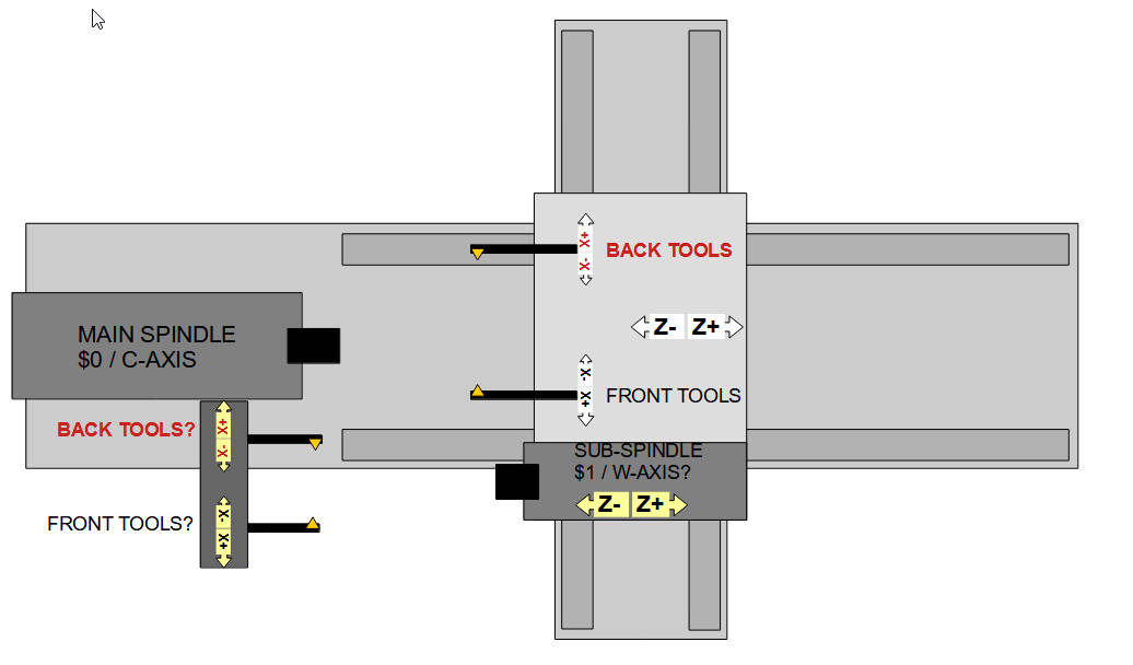
I just sketched up the general arrangement, and I think the Z-pos/neg physical movements won't change when the sub is active.
The display will be off if I can't flip Z around X, but that's not nearly as headache-inducing as having to reverse all Z-movement gcode.
Not sure about front/back tools for the sub tooling, though.
Attachments:
Please Log in or Create an account to join the conversation.
- Aciera
-
- Away
- Administrator
-
- Posts: 4769
- Thank you received: 2138
Please Log in or Create an account to join the conversation.
- spumco
- Offline
- Platinum Member
-
- Posts: 2126
- Thank you received: 882
Maybe, which is why I drew it up to try to straighten it out in my head. I think I've got it drawn correctly but it may also depend on some other settings (like M3/M4 for sub-spindle).Well, wouldn't sub-spindle with back-tool be kind of the same movement as main-spindle with front-tool?
If I mentally flip the lathe along the x axis, the sub front tool still lines up with the main spindle front tool. Z+/Z- stay the same, and if I follow the standard cartesian X/Y/Z rule, X+ is still "down" in the picture.
Meaning a 'front tool' for the sub spindle is the same as a 'front tool' for the main spindle.
Tool orientation isn't really important at the moment, but every question I have - like the sub axis name - gets my brain fizzing with related questions.
And it looks like the backplot view is changeable on the fly with more than just screen buttons, at least for some GUI's like qtvcp and qtpyvcp. I'm guessing that'll be another multi-week rabbit hole once I get there, but if it's possible then I could include some sort of backplot flip as part of the sub-spindle axis engage/disengage M-code dance.
So...
- Sub-spindle will be "W" axis
- Do not need to rotate around X for sub-spindle Z-movements to be rational
- G10 Y-axis rotation hack will still work for sub-spindle back-tools (if needed)
Lots to be done now, but I can get back to wiring & labeling.
Thanks all.
Please Log in or Create an account to join the conversation.
- Aciera
-
- Away
- Administrator
-
- Posts: 4769
- Thank you received: 2138
Yes, I just realized that the tool marked 'BACK TOOLS?' is actually a front tool (geometrically) and 'FRONT TOOLS?' is a back tool.Meaning a 'front tool' for the sub spindle is the same as a 'front tool' for the main spindle.
To run in synchronized mode main spindle will run in M3 while sub spindle will run in M4 and vice versa which should not be a problem, I think.
Please Log in or Create an account to join the conversation.
- spumco
- Offline
- Platinum Member
-
- Posts: 2126
- Thank you received: 882
Yes, I just realized that the tool marked 'BACK TOOLS?' is actually a front tool (geometrically) and 'FRONT TOOLS?' is a back tool.
I drew it as an overhead view of a conventional flat-bed lathe like LCNC thinks it should be.
But for a slant-bed CNC turret lathe, the 'back-tools' shown on the slide would, as you pointed out, be front tools. And vise versa.
Because mine will be a (almost vertical) slant bed arrangement, I think a 'standard' front tool will be considered a 'back tool' in LCNC for backplot purposes.
'standard' front tool: tool above part, X-neg will be down, M3 is CCW (viewed from tail end), and insert cutting edge away from operator.
'standard' back tool: tool below part, X-neg will be up, M3 same, insert edge facing operator
Throw in the fact that I'll probably use a boring bar as both ID and OD work (flipping the spindle from M3 to M4) to save space, it'll get fussy to set this thing up.
I love lathes, but they can make my head hurt.
Please Log in or Create an account to join the conversation.
- Aciera
-
- Away
- Administrator
-
- Posts: 4769
- Thank you received: 2138
Please Log in or Create an account to join the conversation.