Retrofitting a 1986 Maho MH400E
- Glemigobles
- Offline
- Elite Member
-

- Posts: 201
- Thank you received: 18
following error 1 - set P to get this value at the requested acc.
nod point - set I to decrease following error above this value
following error 2 - don't yet understand what to do with it
For Philips machine constants, these values are entered in microns and are very large (5,555mm, 2mm, 12mm). One thing to keep in mind is that the original controller stopped between lines of g-code for a set time in miliseconds, also entered in the MC. This made sure that the slide stopped at the correct point before continuing (gave time for the position loop to complete the move in the programmed place). Dunno how this would work with the trajectory planner and following errors.
I also think that your cutting problems might be related to the velocity curve of the moves calculated from your .ini file. Over time while milling a program such as your pendant housing (2 hours), the commanded feed is actually realised for a percentage of the time, while the remainder consists of moves in material at slower speeds that are the controller-derived ramps (joint.velocity-cmd trapezoid in halscope). That's bad for tool wear.
There's also the matter of the servo loop making a lot of miniscule corrections that might affect the stable operation of the drives. This is ofc pure conjecture on my part, which I'm taking from the perceptible and audible differences between various PID parameters I tested. In my case, the drives seem to be working much harder than they had, to achieve a comparatively far worse result. I can't imagine that it wouldn't have some effect on the machine's output, especially over a longer period.
Now in the case of your pendant housing, the endmill makes a lot of circular and helical moves and I'd wager that it's not always moving as fast as you programmed and that these slower feeds add up in the form of tool wear.
I can help you with your feeds and speeds for the new endmill, but first please check it for manufacturer and catalog number, or tell me whether the endmill is HSS (probably not), HSS-Co (cheaper) or HSS-PM (more expensive, superior performance). Also check for coating. These things make for a world of difference in setting the correct feeds and speeds.
EDIT: the tool info is usually there in some form on the cutter itself, you don't need the original box.
Please Log in or Create an account to join the conversation.
- RotarySMP
-
 Topic Author
- Offline
- Platinum Member
-

- Posts: 1630
- Thank you received: 595
I guess if you have an absolute stop at the end of every line of code, then Ferror on linear moves is irrelevant and can be very large, as the path is always correct, just a little behind during accel and then ahead during decel.. The only place where the Ferror could cause a deviation between the commanded path, and the actual tool path would be during G2/3 curves at high feedrates.
The trajectory planner of LinuxCNC is far more sophisticated, you define a width of the acceptable tool path tolerance, my simplistic understanding is that it will match the feedrate to the machines dynamic performance to remain within those boundaries.
Good point that my sluggish tuning is probably bad for cutter life. My presence is generally bad for cutter life
")
I can help you with your feeds and speeds for the new endmill, but first please check it for manufacturer and catalog number, or tell me whether the endmill is HSS (probably not), HSS-Co (cheaper) or HSS-PM (more expensive, superior performance). Also check for coating. These things make for a world of difference in setting the correct feeds and speeds.
EDIT: the tool info is usually there in some form on the cutter itself, you don't need the original box.
Too late, I already milled it out. Worked fine at 240 mm/min. The cutter is a Chinese end mill from CTCtools.biz. No info on the type of HSS (Assume no Co),no coating and no recommended cutting parameters. At €6 pop, you can see why I am pretty relaxed about killing them. I figured I'm better off using cheap cutters, until I get enough feel for the machine to stop doing the really stupid beginner mistakes (I killed two carbides - one be jogging it into steel, the second by letting it bounce lightly on work during tool release.


Please Log in or Create an account to join the conversation.
- Glemigobles
- Offline
- Elite Member
-
- Posts: 201
- Thank you received: 18
Normally, German HSS cutters of this diameter are in the 20-35€ range, now I get your easy come easy go attitude about all this. You can sometimes buy tool lots at good prices from places like surplex, which I think would be a pretty good deal if you have a tool grinder.
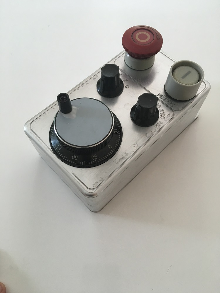
With this pendant design I would recommend getting a Haimer/Mahr 3d taster for work offsets. You'll be able to stand close enough to the touchscreen to select axis and offset values since these devices have large dials. It saves you from having to see the material edge and distance, while the pendant still allows for precision control in small increments. The original pendant was similar in that regard (but with Linux it's not necessary to memorize values before entering them to the offset table; big win in my book, standard feature on all modern controllers).
I noticed just now that the MC values set following errors for maximum output voltage from the NC. That's why the Philips values are so large. So maybe tuning can go like this: set up an acceleration value from the range suggested by Indramat, increase the axis following error to a large value (probably some 20mm), set PID to 0, command rapid traverse, measure the error in halscope, compare to sample MCs from the MH500C, adjust PID with that range.
The output voltage in the MCs is listed as 9V because Indramat recommends there should be some wiggle room in case of overshoots from the NC. So all these parameters and the servomotors are set up for lower assumed voltages than 10V. Idk if that has any bearing on anything, but I will assume that it's better not to retune the servos themselves and just limit tinkering to the Linux side of things.
Please Log in or Create an account to join the conversation.
- PCW
-

- Offline
- Moderator
-

- Posts: 17976
- Thank you received: 5275
gnipsel.com/linuxcnc/tuning/servo.html
The primary tuning parameter for velocity mode drives is FF1
FF1 can be tuned with a small P value
it is independent of P and the error caused by too high
or too low FF1 are more visible when P is small
Basically FF1 (when correct) sets the drives velocity per
servo period to LinuxCNCs velocity (no feedback involved)
So with just FF1 you are "dead reckoning" and will drift out of position
because
1. The drives drift
2. The velocity command is not precise
3. The timing is not precise
4. The velocity feedback in the drives is inaccurate
This is where the proportional feed back (P term) comes in
to correct the errors above, but FF1 is still the primary tuning
parameter for velocity mode drives
Please Log in or Create an account to join the conversation.
- Glemigobles
- Offline
- Elite Member
-
- Posts: 201
- Thank you received: 18
Yes, I've been tuning the axes like that before. Now I'm trying to compare these results with the original performance before the retrofit. The point was that we want the acceleration to be within the drives' recommended values but it would seem that presupposes a much higher following error. I'm trying to figure out what values for following errors are acceptable based on the old documentation and settings.
It seems to me that it might be possible to "overtune" a drive, limiting its performance by being too stringent with the errors. It's very audible in my case, I can hear how different PID affect the drive's idle state. BTW, I should've said that earlier, I'm using PID as a shorthand for the tuning parameters. I haven't really tried using I or D. It's just easier to write than P, ferror1 and ferror2.
Mark, if when you have an opportunity, please take a picture of your encoder connections to the Mesa card. I think my wiring sucks - I started the machine today and the Z encoder didn't register changes in the slide position. Then I switched it off, checked the wires, took out the TB, put it back in again and it works. I think I should provide better shielding or something, I'm curious to see how a pro made the physical wiring. The original D-sub terminals were massive metal shells, unlike anything I'd seen, I'm sure they provided superb noise shielding and stability.
Please Log in or Create an account to join the conversation.
- PCW
-
- Offline
- Moderator
-
- Posts: 17976
- Thank you received: 5275
Too high P term will result in buzzy/rough control, too low will have more following error so its always a compromise. You can reduce dithering at idle by adding some deadzone.
If unplugging/plugging the Z encoder connector fixes a non-working encoder I would
1. Make sure you don't have a loose wire on the connector (its easy to get the wire on
the wrong side of the rising clamp if you don't completely loosen the screw before
inserting the wire)
2. If #1 doesn't fix your problem, replace the Z encoder connector
Please Log in or Create an account to join the conversation.
- Glemigobles
- Offline
- Elite Member
-
- Posts: 201
- Thank you received: 18
Regarding the performance, I did work on this machine for over 1,5 years before plunging into this retrofit. Deadzone is an excellent idea I wasn't aware of.
I know that the acceleration rates were supposed to be higher than what Mark set, and when I tried to increase them I came up with low values as well because I wathced the error value too closely.
It turns out that the recommended acceleration for the Indramats was ca. 220 mm/sec2, and that the machine had following errors orders of magnitude larger than what I was trying to force on it.
Please Log in or Create an account to join the conversation.
- Glemigobles
- Offline
- Elite Member
-
- Posts: 201
- Thank you received: 18
This is kind of a forced rapid traverse, I'm just using G1 at the requested feedrate.
At present, Y and Z achieve measured acceleration rates in the vicinity of the recommended Indramat specs, but X lags behind at over 320 ms until 3000 mm/min is achieved. I think the other axes are doing better only because their max feedrates are slower due to finder ballscrew pitch.
Anyway the machine is starting to sound and behave much more like before the retrofit. I'd be curious to hear how you can do Mark.
Please Log in or Create an account to join the conversation.
- RotarySMP
-
Topic Author
- Offline
- Platinum Member
-
- Posts: 1630
- Thank you received: 595
When I go up for dinner, I'll post the photos of how I terminated the EXE cables in the MESA 7i77.
Mark
Please Log in or Create an account to join the conversation.
- RotarySMP
-
Topic Author
- Offline
- Platinum Member
-
- Posts: 1630
- Thank you received: 595
Please Log in or Create an account to join the conversation.