Retrofitting a 1986 Maho MH400E
- RotarySMP
-
 Topic Author
- Offline
- Platinum Member
-

Less
More
- Posts: 1633
- Thank you received: 595
19 May 2019 17:36 - 19 May 2019 17:38 #134279
by RotarySMP
Replied by RotarySMP on topic Retrofitting a 1986 Maho MH400E
Tuning the X Axis with :
Accel 220
P= 4.5
FF1 = 2.15
FF2= 0.006
With the feedrate set to 69mm/min during tuning
This is the best I have acheived.
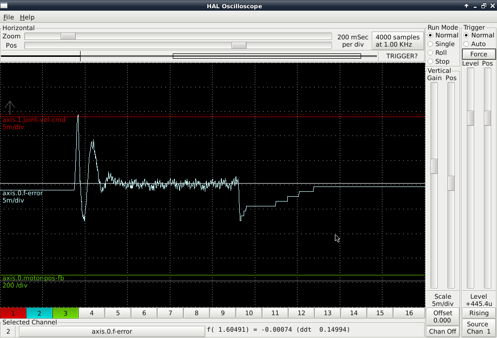
So I am getting following errors of around 15µm at very low feed rates. That seems pretty bad to me.
I tried Accel 270, but it is worse. With max velocity of 3000mm/min, the machine has near instant accel/decel, but with pretty bad following errors.
Mark
Accel 220
P= 4.5
FF1 = 2.15
FF2= 0.006
With the feedrate set to 69mm/min during tuning
This is the best I have acheived.
So I am getting following errors of around 15µm at very low feed rates. That seems pretty bad to me.
I tried Accel 270, but it is worse. With max velocity of 3000mm/min, the machine has near instant accel/decel, but with pretty bad following errors.
Mark
Last edit: 19 May 2019 17:38 by RotarySMP.
Please Log in or Create an account to join the conversation.
- Glemigobles
- Offline
- Elite Member
-

Less
More
- Posts: 201
- Thank you received: 18
19 May 2019 17:49 #134280
by Glemigobles
Replied by Glemigobles on topic Retrofitting a 1986 Maho MH400E
I tuned at rapid rates, and then when I checked the following error on slower speeds it was much better than the rapid results
Please Log in or Create an account to join the conversation.
- RotarySMP
-
Topic Author
- Offline
- Platinum Member
-
Less
More
- Posts: 1633
- Thank you received: 595
19 May 2019 17:53 - 19 May 2019 18:39 #134281
by RotarySMP
Replied by RotarySMP on topic Retrofitting a 1986 Maho MH400E
The recommendations are all to start tuning slow. Could please post a screen shot of the Ferror of an X axis move at 69mm/min, so that we can compare apples to apples.
Last edit: 19 May 2019 18:39 by RotarySMP.
Please Log in or Create an account to join the conversation.
- RotarySMP
-
Topic Author
- Offline
- Platinum Member
-
Less
More
- Posts: 1633
- Thank you received: 595
19 May 2019 18:34 - 19 May 2019 18:38 #134282
by RotarySMP
Replied by RotarySMP on topic Retrofitting a 1986 Maho MH400E
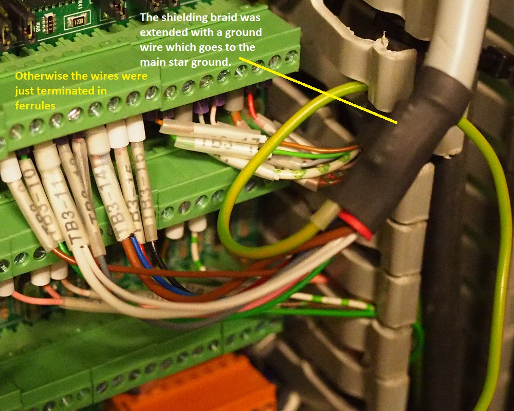
Remember I know squat about electrical stuff. Here is how I terminated each of the EXE output cables into the Mesa 7i77. I butchered the cables, chopping off the original connectors. Use a ferrule to connect an earthing wire to the shielding braid, and ran all of them to the main star ground on the bottom RH side of the cabinet, to hopefully prevent ground loops.
The lid for the pendant got made first.
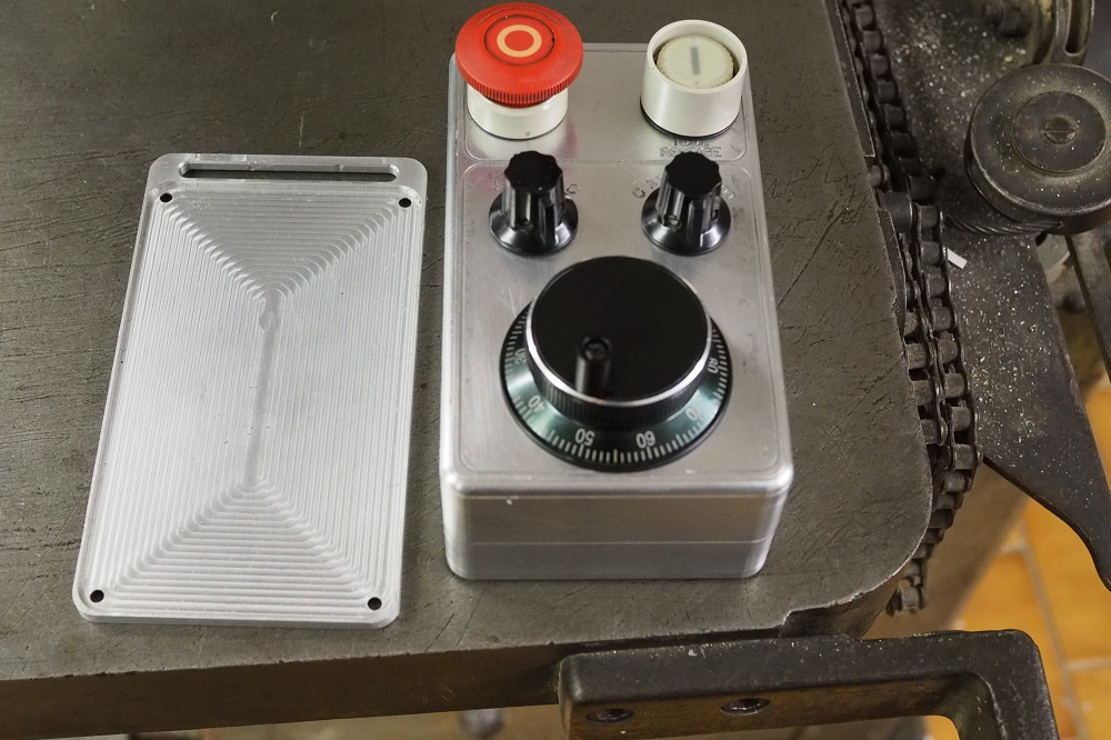
The lid for the pendant got made first.
Attachments:
Last edit: 19 May 2019 18:38 by RotarySMP.
The following user(s) said Thank You: Glemigobles
Please Log in or Create an account to join the conversation.
- Glemigobles
- Offline
- Elite Member
-
Less
More
- Posts: 201
- Thank you received: 18
20 May 2019 11:34 - 20 May 2019 11:36 #134346
by Glemigobles
Replied by Glemigobles on topic Retrofitting a 1986 Maho MH400E
Thanks for the pictures.
I get a 16 micron spike at the beginning of a move if I program the X axis to go at a feedrate of 69 mm/min. But then it flattens out almost entirely and there's no spike or dip at the end.
Maybe I should lower the acceleration on that particular axis since the higher value didn't actually help in making it start faster.
On other feeds the biggest error is the spike at the start and it varies across feedrates.
Overall, I'm pleased with the results of following the original manuals. Remember they only gave you 2 types of gain to adjust the following error, and they recommended doing (at least a part of the tuning, I don't remember) tuning at rapid feeds.
In the constants you posted, the following error that engaged the second type of gain was 2 mm. I treated gain 1 as P and gain 2 as ferror_1, and also added ferror_2 for good measure.
From the Philips manual, if the error values were large, it meant that the outputted gains were low. All my P gains are below 8, and the ferror adjustment I found to be very touchy and prone to making enormous changes with very small increments, so it's a good idea to go 5 or 6 decimal points to fine tune it.
Bizzarely, after tuning the axes for the previous accelerations, inputting the larger ones made very little difference to the waves shown by the oscilloscope.
Setting the deadband to 0,001 reduced servo hunting on X and Y, made the machine sound a little better.
EDIT: I didn't make it clear and it's important to note, following error values 1 and 2 from the Philips MCs determine the gain and are proportional. They had you enter the errors instead of the gains, the controller set the the gains based on the errors you inputted.
Last edit: 20 May 2019 11:36 by Glemigobles.
Please Log in or Create an account to join the conversation.
- andypugh
-

- Offline
- Moderator
-

Less
More
- Posts: 19879
- Thank you received: 4643
20 May 2019 11:56 #134348
by andypugh
Replied by andypugh on topic Retrofitting a 1986 Maho MH400E
Bear in mind that a 15um spike on starting might not mean that the cutter is 15um off-path. The chances are that it is on the path, but not in the place on the programmed path that it should be.
The will only matter on coordinated moves, for example a sharp corner might show 15um of rounding.
The will only matter on coordinated moves, for example a sharp corner might show 15um of rounding.
Please Log in or Create an account to join the conversation.
- Glemigobles
- Offline
- Elite Member
-
Less
More
- Posts: 201
- Thank you received: 18
20 May 2019 12:07 - 20 May 2019 12:16 #134349
by Glemigobles
Replied by Glemigobles on topic Retrofitting a 1986 Maho MH400E
Ran my first test program from Fusion360 and immediately crashed the spindle into the table 
I didn't notice that before the actual milling starts and G54 is loaded, the program explicitly tells the machine to G0 Z0, WTF Autodesk!?
The bearings seem to run okay still, but all the screws holding it in the bracket broke. I have grown too complacent with CAM.
And yet in the actual bore a hole program, all the Z directions are programmed in the correct direction. When the hole is complete, the spindle retracts to Z15 and then, again, G53 Z0! I am lost for words.
Also I guess the fact that I had Feed override set to 0 meant precious nothing when running individual blocks from the autorun menu.
Last edit: 20 May 2019 12:16 by Glemigobles.
Please Log in or Create an account to join the conversation.
- andypugh
-
- Offline
- Moderator
-
Less
More
- Posts: 19879
- Thank you received: 4643
20 May 2019 13:06 #134353
by andypugh
Replied by andypugh on topic Retrofitting a 1986 Maho MH400E
It is probably wise to configure the Z axis to have zero at the top and negative numbers towards the bottom.
I think this is the (dangerous) assumption that Inventor / Fusion / HSM CAM makes.
It's worth noting that LinuxCNC also makes this assumption if you configure TOOL_CHNGAE_QUILL_UP
linuxcnc.org/docs/2.7/html/config/ini-co....html#_emcio_section
(mentions G53 G0 Z0)
So I guess it is a common enough convention.
Please Log in or Create an account to join the conversation.
- Todd Zuercher
-

- Away
- Platinum Member
-
Less
More
- Posts: 4761
- Thank you received: 1463
20 May 2019 13:21 #134356
by Todd Zuercher
Replied by Todd Zuercher on topic Retrofitting a 1986 Maho MH400E
On most cnc's, it is actually fairly normal procedure for the beginning of a file to do a G53 Z0 move to move the Z to a safe known height. (Since most machines have the machine Z0 configured for the top of Z travel.)
Please Log in or Create an account to join the conversation.
- Glemigobles
- Offline
- Elite Member
-
Less
More
- Posts: 201
- Thank you received: 18
20 May 2019 14:07 #134358
by Glemigobles
Replied by Glemigobles on topic Retrofitting a 1986 Maho MH400E
Well, this machine has a limit switch at 400 mm, and that's how I configured it. Fusion did not insert a Z0 block in the headers of programs for the Philips controller, but that's a matter of post processors, so there you go. I got used to there being no movement in the header, looked up G54 and the values after that and thought I was safe. If this was a job, I'd get fired.
Fortunately, the material into which it crashed was plastic, taped to an aluminum board. I imagine the damage would have been far more severe if it crashed into the machine's work table directly.
Fortunately, the material into which it crashed was plastic, taped to an aluminum board. I imagine the damage would have been far more severe if it crashed into the machine's work table directly.
Please Log in or Create an account to join the conversation.
Moderators: piasdom
Time to create page: 0.609 seconds