Regarding indramat mdc motors and 3trm2 drive
- Sourabh3
- Offline
- Senior Member
-

Less
More
- Posts: 73
- Thank you received: 1
30 Jan 2021 12:23 #197150
by Sourabh3
Regarding indramat mdc motors and 3trm2 drive was created by Sourabh3
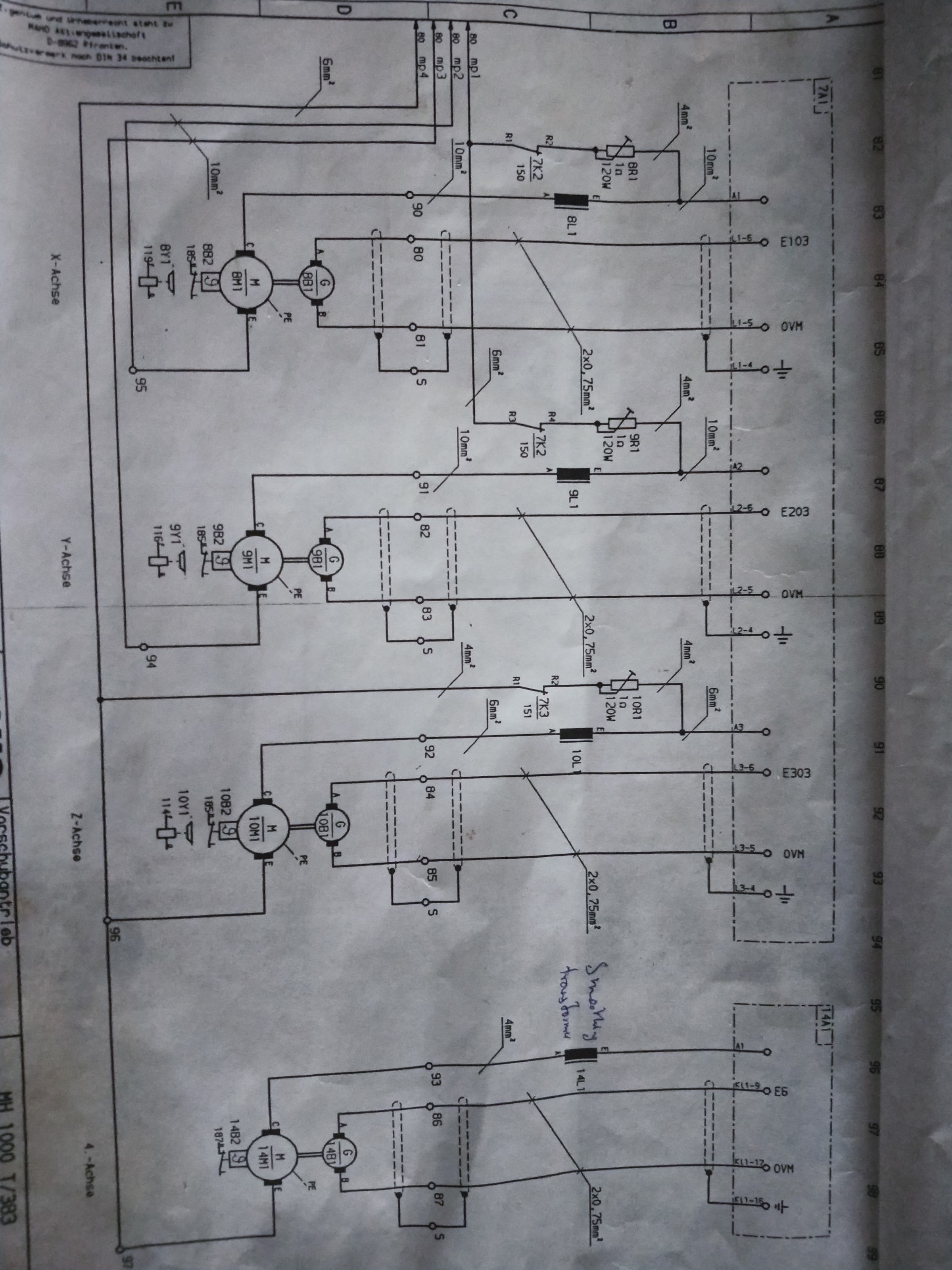
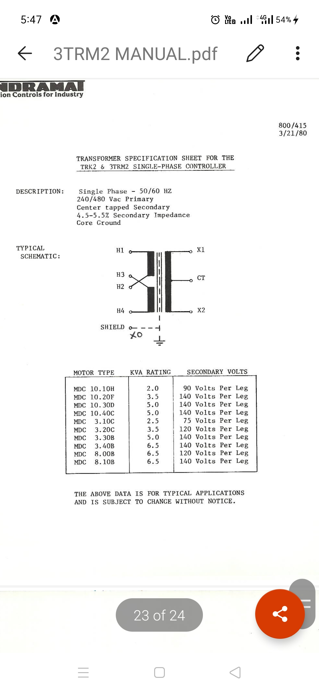
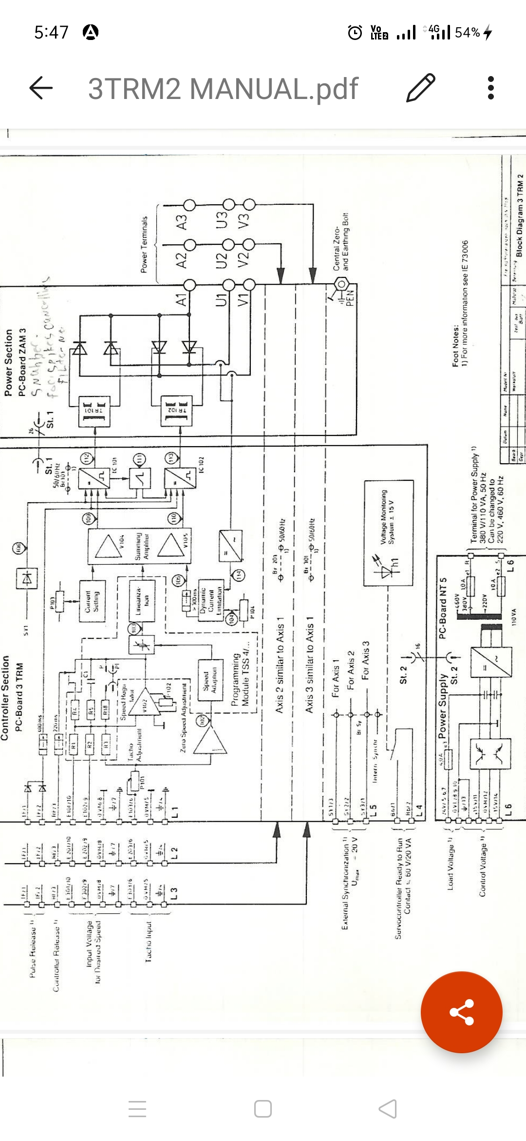
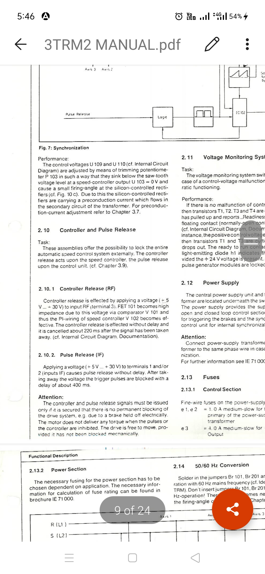
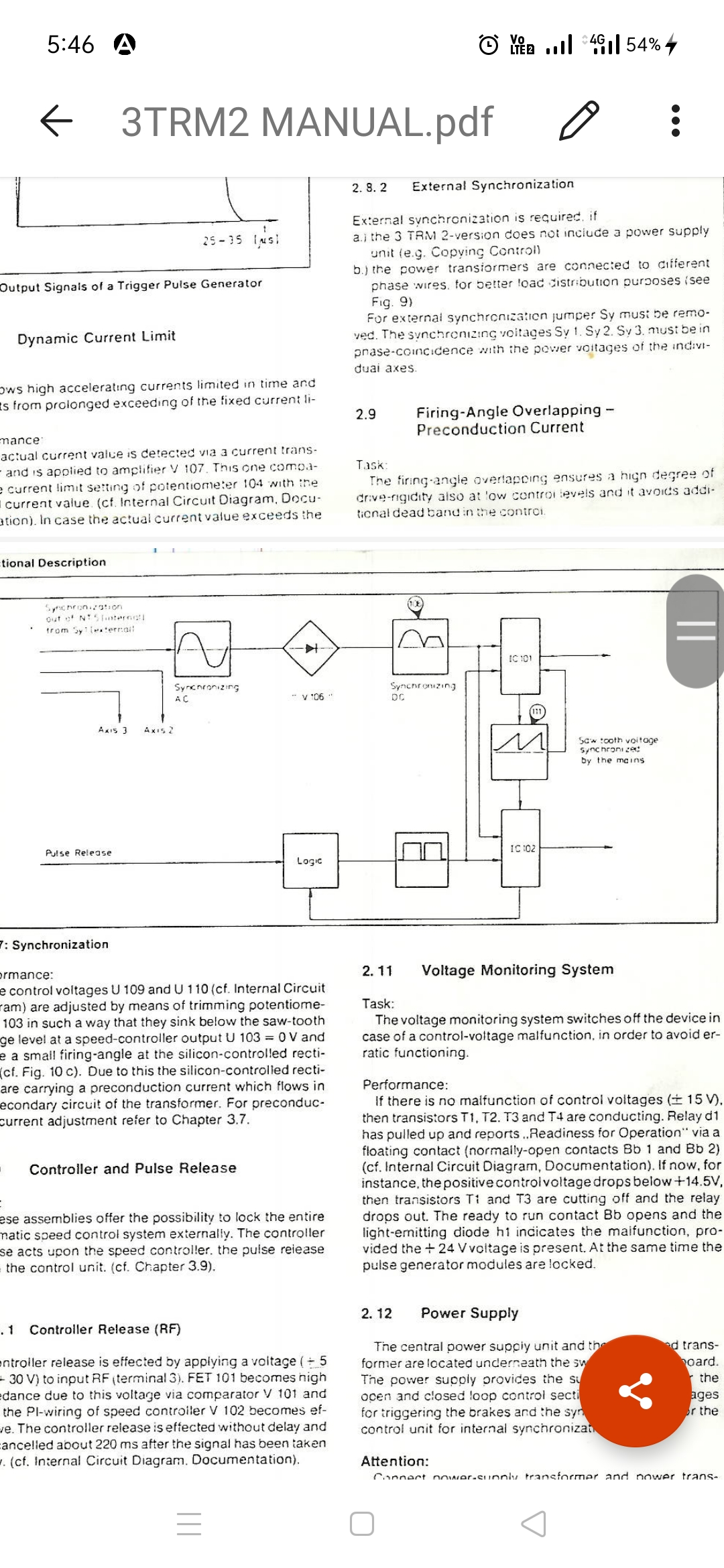
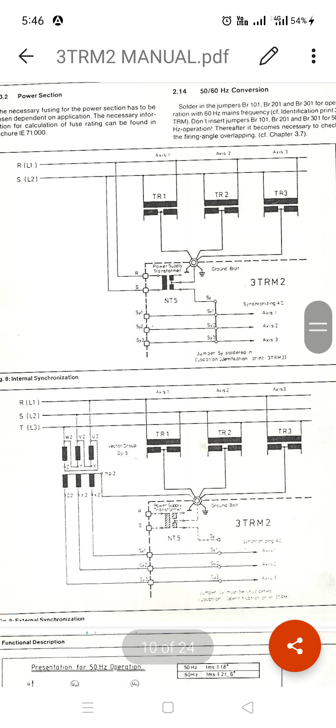
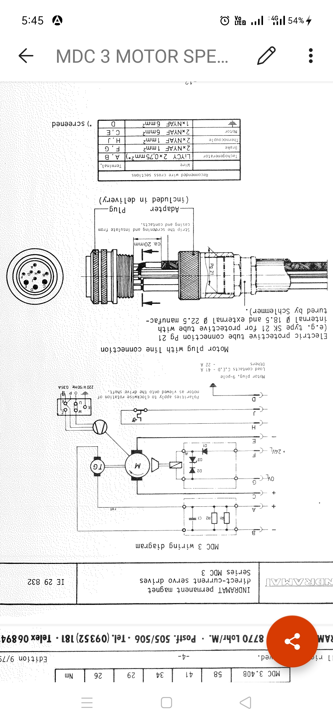
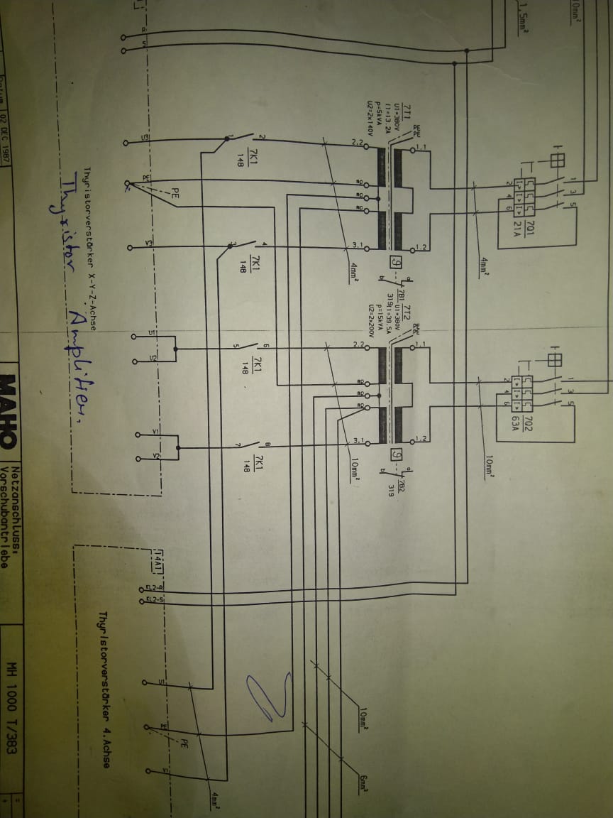
I have a old maho and I'm planning to retrofit it with linux cnc using mesa cards. Unfortunately the wiring is ripped off from the system. And i want to use the same 4 indramat mdc 10.40c motors, one 3trm2 drive and one 2trm1 drive. I'm attaching the photos from manual of 3trm2, mdc motor, and some pics from maho manual. My question is, i don't know what "mp" means(in maho manual pics near 7t2 transformer.... Not mentioned on the transformer either). Can anyone please tell me wiring for "U", "V" and "A" terminals to the motor.... Using the smoothing transformer and the resistance? I'm a bit confused withthe 4th axis motor wiring (2trm1) and 3rd axis in 3trm2.
Attachments:
Please Log in or Create an account to join the conversation.
- andypugh
-

- Offline
- Moderator
-

Less
More
- Posts: 19875
- Thank you received: 4642
31 Jan 2021 01:43 #197190
by andypugh
Replied by andypugh on topic Regarding indramat mdc motors and 3trm2 drive
I can't see MP near the 7T2 transformer.
And, equally unhelpfully, I don't know what U, V and A are.
UVW are generally used as the three phases of a three phase motor, but these seem to be DC motors.
And, equally unhelpfully, I don't know what U, V and A are.
UVW are generally used as the three phases of a three phase motor, but these seem to be DC motors.
Please Log in or Create an account to join the conversation.
- Henk
- Offline
- Platinum Member
-

Less
More
- Posts: 408
- Thank you received: 92
31 Jan 2021 03:34 #197199
by Henk
Replied by Henk on topic Regarding indramat mdc motors and 3trm2 drive
I have a maho with that same 3trm2 drive,without the 4th axis and the additional drive.
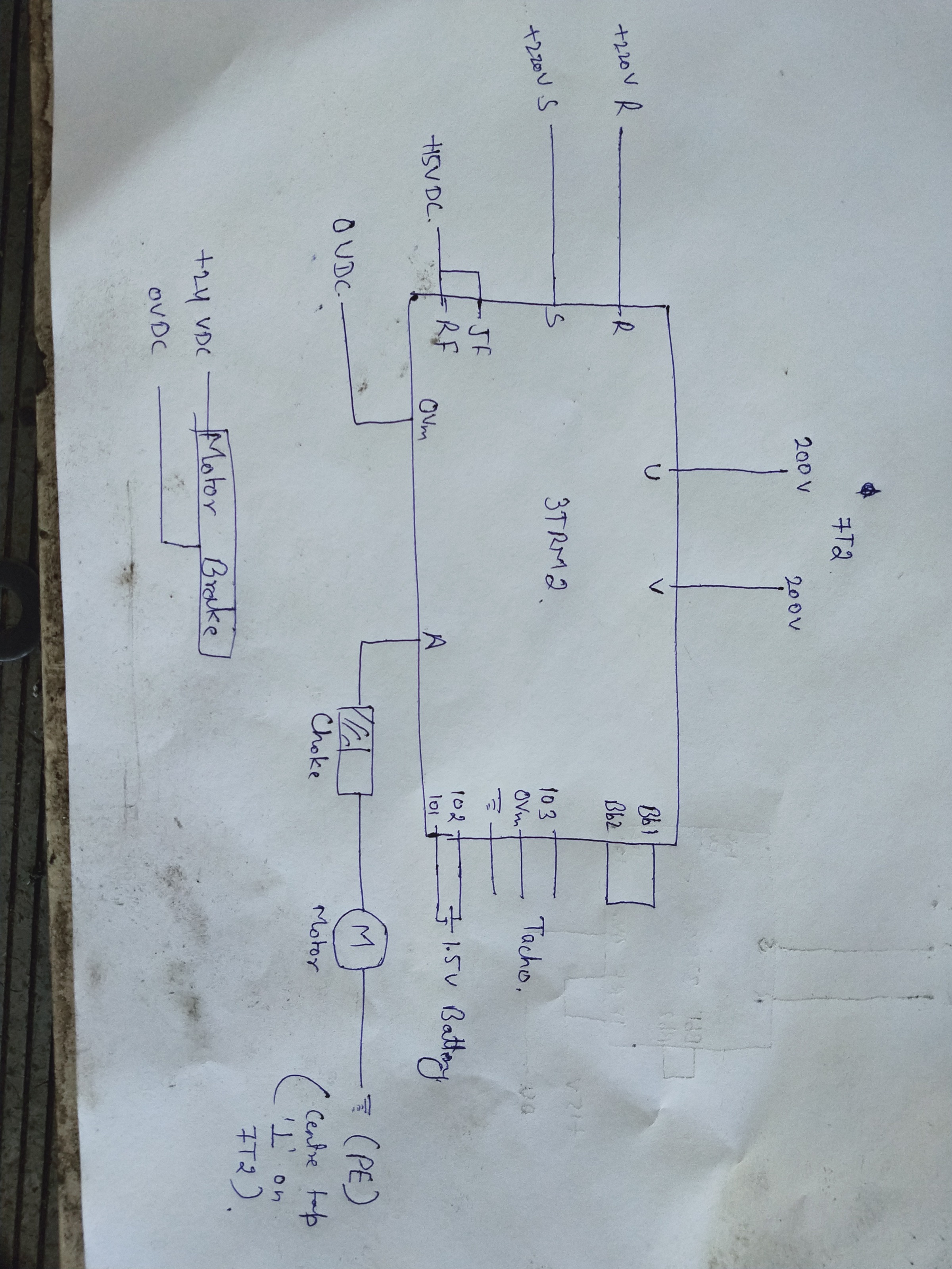
The transformer that feeds the drive is single phase output with a centre tap. The centre tap is connected to the drive frame which is also machine ground. One of the motor leads is also connected to this tap, while the other is connected to A1. 2nd motor to A2 and so on. Some of these drives have seperate U and V terminals for each axis marked U1 U2 U3 and same for V. Others have a common U and V terminals.
U and V is connected to the other two taps on the transformer which is the power supply to the drive for driving the motor. That's is also another power supply for the control side on the drive.
I think the resistor you are referring to is a braking resistor that shorts the motor armature when you press Estop. Under normal running they are bridged. Is mp1 to 4 not just referring to another page?
Henk
Please Log in or Create an account to join the conversation.
- Sourabh3
- Offline
- Senior Member
-
Less
More
- Posts: 73
- Thank you received: 1
31 Jan 2021 04:30 - 31 Jan 2021 04:41 #197202
by Sourabh3
Replied by Sourabh3 on topic Regarding indramat mdc motors and 3trm2 drive
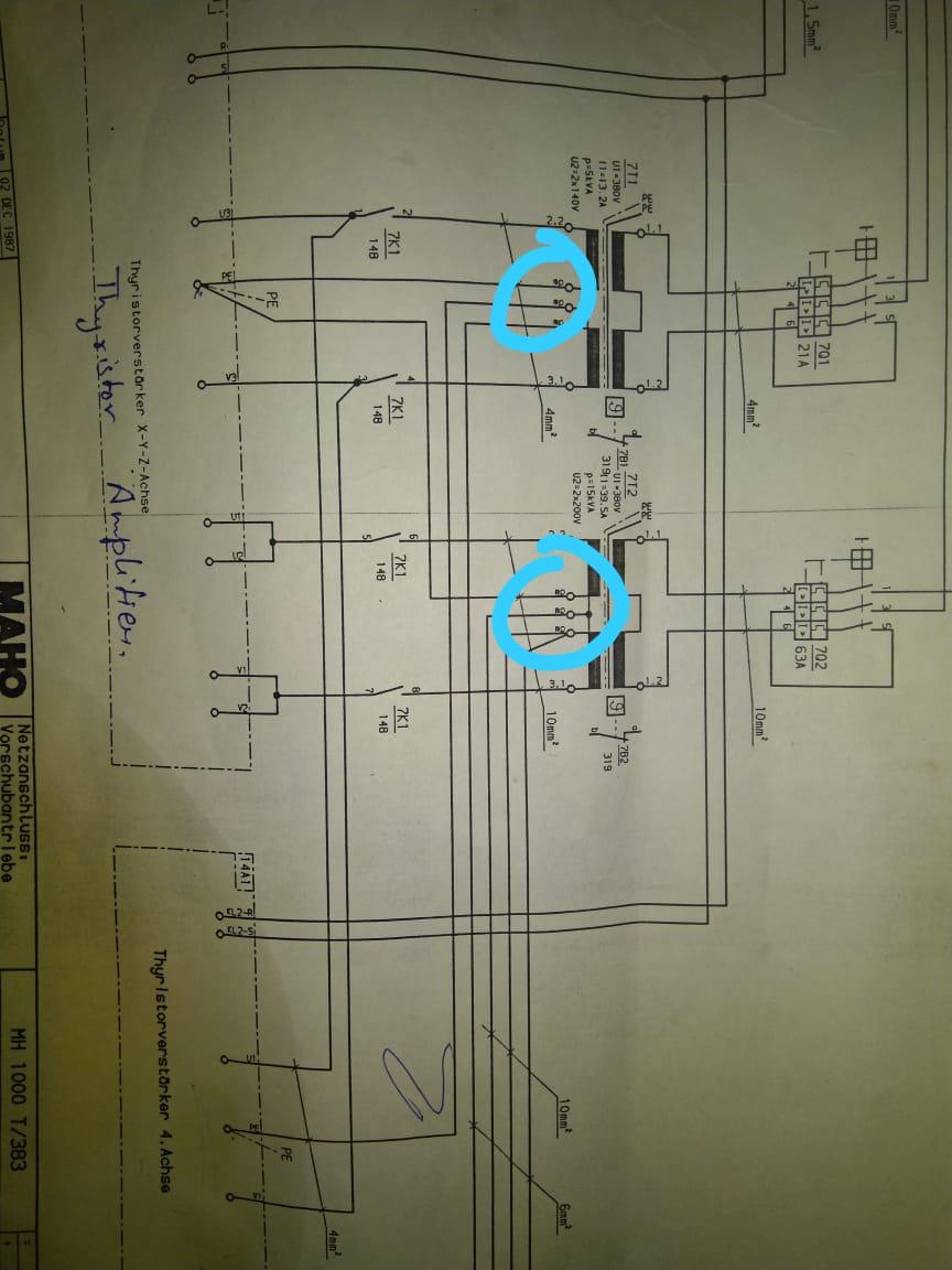
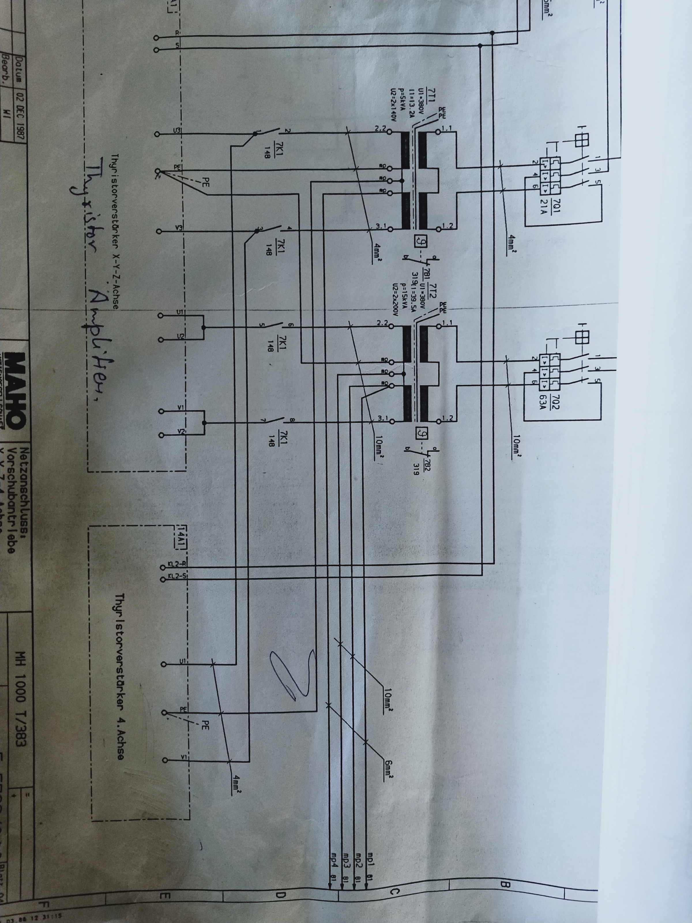
Your knowledge is really good. Thanks for helping me out. The "mp" connection is connected with the ground. Do you think this mp is the centre tap? I have attached the picture of "other page" as you asked. Can you just tell me wiring from A1 to motor ( through resistor and smoothing transformer)? I have already connected U and V. I just want to know how can i connect the motor with this drive?

Last edit: 31 Jan 2021 04:41 by Sourabh3.
Please Log in or Create an account to join the conversation.
- Henk
- Offline
- Platinum Member
-
Less
More
- Posts: 408
- Thank you received: 92
31 Jan 2021 04:42 #197203
by Henk
Replied by Henk on topic Regarding indramat mdc motors and 3trm2 drive
I would connect it the same as shown in your diagrams. Mp is the centre tap. So when 7k2 is closed there is a 1ohm resistor over the motor leads and it will stop fast. 7k2 must open before the drive is enabled. So wire this in your Estop circuit. Drive must only be enabled after 7k2 is open. A1 must go through the choke or what you call smoothing transformer BL1 always regardless of whether 7k2 is open or closed.
Please Log in or Create an account to join the conversation.
- Sourabh3
- Offline
- Senior Member
-
Less
More
- Posts: 73
- Thank you received: 1
31 Jan 2021 06:59 #197205
by Sourabh3
Replied by Sourabh3 on topic Regarding indramat mdc motors and 3trm2 drive
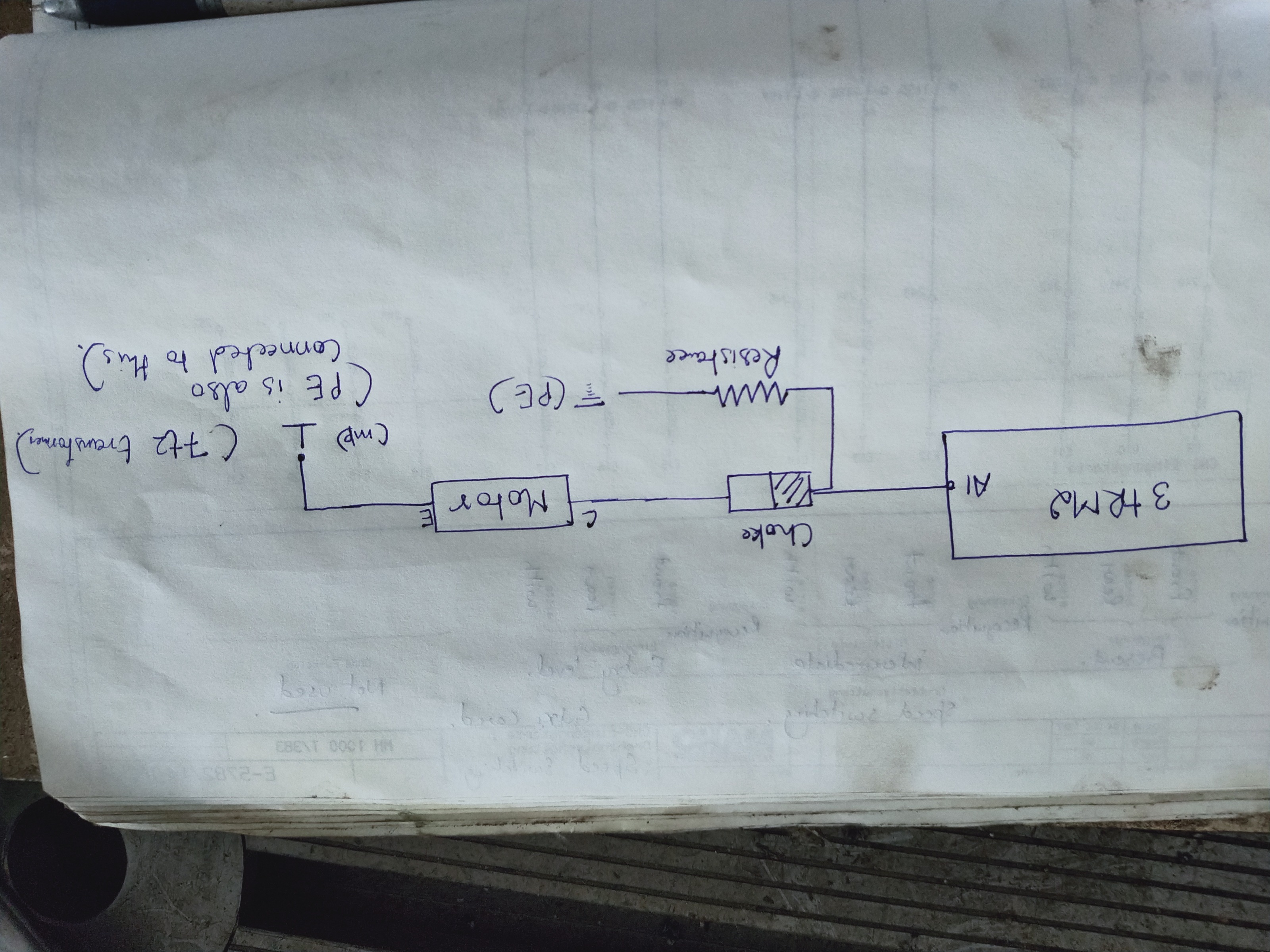
Please look at this picture. (leave 7k2 and 7k3 out of the loop for now). This is what I have understood by far. Is this correct? Can i test the drive with a cell on analog input terminals(without a pot)?
Attachments:
Please Log in or Create an account to join the conversation.
- Henk
- Offline
- Platinum Member
-
Less
More
- Posts: 408
- Thank you received: 92
31 Jan 2021 07:21 #197206
by Henk
Replied by Henk on topic Regarding indramat mdc motors and 3trm2 drive
Leave the resistor out as well. Connect A1 to the choke and the choke to the motor as shown.
You can use a 1.5v battery to test.
After you enable the drive, if it runs away fast...reverse the tacho feedback wires.
Without feedback from lcnc, the motor will probably drift slowly before you apply the speed ref 1.5v
You can use a 1.5v battery to test.
After you enable the drive, if it runs away fast...reverse the tacho feedback wires.
Without feedback from lcnc, the motor will probably drift slowly before you apply the speed ref 1.5v
Please Log in or Create an account to join the conversation.
- Sourabh3
- Offline
- Senior Member
-
Less
More
- Posts: 73
- Thank you received: 1
31 Jan 2021 08:52 #197211
by Sourabh3
Replied by Sourabh3 on topic Regarding indramat mdc motors and 3trm2 drive
I have plotted a final diagram of the circuit. Please let me know if this is correct. And will this diagram be enough to run the motor (for a test). Let me know if I'm missing something.
Attachments:
Please Log in or Create an account to join the conversation.
Moderators: piasdom
Time to create page: 1.064 seconds