- Hardware & Machines
- CNC Machines
- Milling Machines
- A-M-C A12A100 Servo Drive with SouthWestern Ind ProtoTrak Plus
A-M-C A12A100 Servo Drive with SouthWestern Ind ProtoTrak Plus
- new2linux
- Offline
- Platinum Member
-

Less
More
- Posts: 711
- Thank you received: 9
05 Feb 2021 18:17 - 13 Feb 2021 23:01 #197762
by new2linux
A-M-C A12A100 Servo Drive with SouthWestern Ind ProtoTrak Plus was created by new2linux
I offer my many thanks to moderators and all the other folks, that make this forum so wonderful & educational.
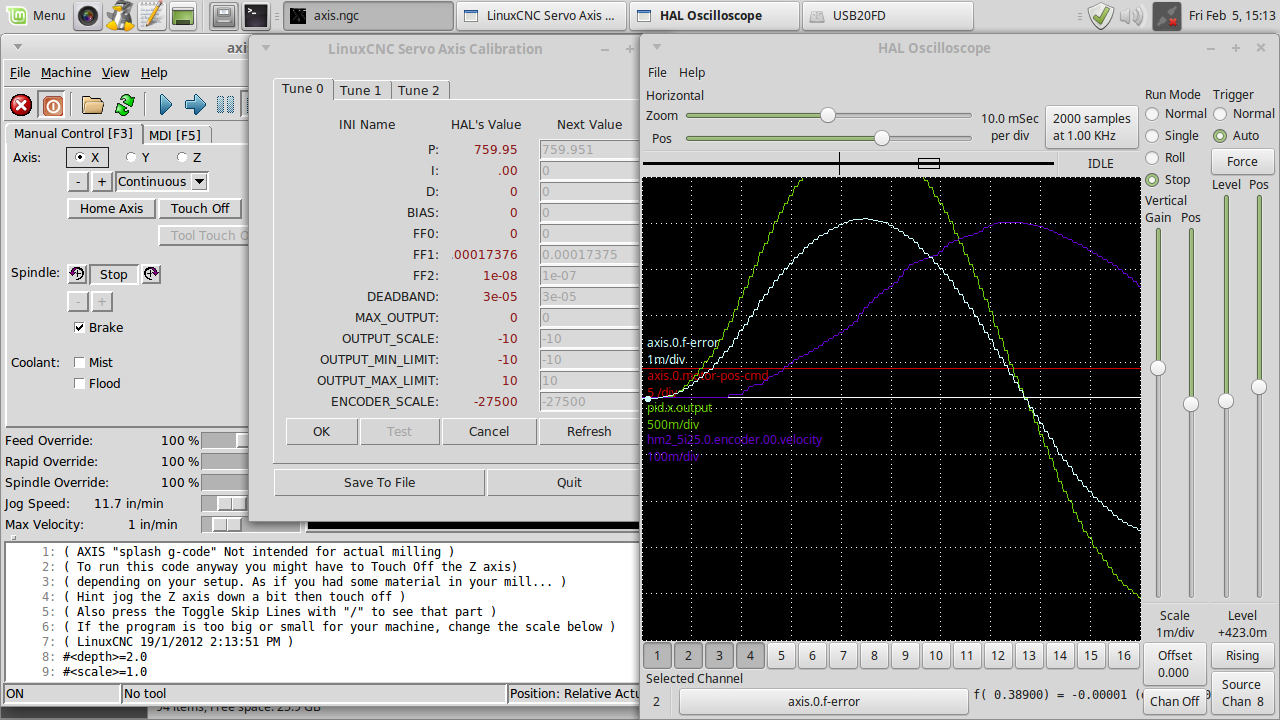
My project is a 2 axes mill with new encoders and drives. The current screen shot I am at the tuning screen for the drive. Attached are the diagram, part numbers and the AMC manual that I have referenced. The set up is for "current mode"; SW1-1, -2 & 4=OFF: POT 1=full CCW; POT 2 full CW (as for motor, 6.25 amp); POT 3 full CW; POT 4 start at mid point (adj offset, no motion).
This is the encoder info:
EM1-2-500-N
HUBDISK-2-500-500-NE
CA-LC5-W4-NC-1
You can find mechanical drawings and pricing for each item on our website here:
www.usdigital.com/products/encoders/incr.../modules/EM1-2-500-N
www.usdigital.com/products/encoders/incr...HUBDISK-2-500-500-NE
www.usdigital.com/products/accessories/cables/CA-LC5-W4-NC-1
The pics of the tuning are of X axes, same feed rate, but the FF1 varies some, but the scales on the scope differ from each other. Any suggestions for tuning would be warmly welcomed.
Edit: This is latest pic of tuning. I understand the f error trace (the light blue) needs to be flat, just need a 2nd opinion:
Last edit: 13 Feb 2021 23:01 by new2linux. Reason: Add:current mode
Please Log in or Create an account to join the conversation.
- Todd Zuercher
-

- Away
- Platinum Member
-
Less
More
- Posts: 4755
- Thank you received: 1458
05 Feb 2021 21:34 #197779
by Todd Zuercher
Replied by Todd Zuercher on topic A-M-C A12A100 Servo Drive with SouthWestern Ind ProtoTrak Plus
What did you command the axis to do when that plot was created? How far? How fast? In which direction?
This is where having a plot of the velocity-cmd comes in handy so we can directly compare that with the velocity feedback (your purple trace.)
You have a plot of the position command but the commanded move is so small that we can't see what it was (the plot line is flat.) and there fore useless.
This is where having a plot of the velocity-cmd comes in handy so we can directly compare that with the velocity feedback (your purple trace.)
You have a plot of the position command but the commanded move is so small that we can't see what it was (the plot line is flat.) and there fore useless.
The following user(s) said Thank You: new2linux
Please Log in or Create an account to join the conversation.
- new2linux
- Offline
- Platinum Member
-
Less
More
- Posts: 711
- Thank you received: 9
06 Feb 2021 16:32 - 08 Feb 2021 12:44 #197845
by new2linux
Replied by new2linux on topic A-M-C A12A100 Servo Drive with SouthWestern Ind ProtoTrak Plus
Andy, Many thanks. This I believe this has the changes that you suggested. There are 2 of the same settings, big pic and all together.
I have read this by JR1050 (many thanks!!), late last night, and have included some pics as well, the file/pic name has the settings if not in the pic, never got reed rate greater than 15"/min or about.
"Current mode is a pain and requires much higher gains then velocity mode, my experience with these type drives and current mode is set p until the motor oscillates then back off, set d until you get a crisp start and stop(no overshoot " critically dampened"). On velocity drives I usually set ff1 to 1.0 and add a tiny amount of p gain until the motor is stiff as possible with out overshoot. Somewhere there is a vey good thread about motor tuning and gains by Andy and I wanna say that current mode drives use ff0, but Im not swearing to it. Id start my p gain at 100 . and d at 1 in current mode."
Many thanks, all help warmly welcomed.
Update 20"/min; last pic. The settings are the file name.
Many thanks!
Last edit: 08 Feb 2021 12:44 by new2linux. Reason: Add pic, add 2nd set of pics
Please Log in or Create an account to join the conversation.
- Todd Zuercher
-
- Away
- Platinum Member
-
Less
More
- Posts: 4755
- Thank you received: 1458
08 Feb 2021 19:40 #198055
by Todd Zuercher
Replied by Todd Zuercher on topic A-M-C A12A100 Servo Drive with SouthWestern Ind ProtoTrak Plus
You need a lot more I term, and probably more FF2. I couldn't even venture a guess as to how much more of these. (in current mode FF2 behaves more like FF1 does in a velocity command system, so should help with the steady state error.)
You may also find it beneficial to limit the error input for the I-term using "pid.N.maxerrorI" Use the smallest value for this hal pin that still allows the I term to max out the PID command. (Doing this prevents I term windup and reduces the resulting overshoot.)
You may also find it beneficial to limit the error input for the I-term using "pid.N.maxerrorI" Use the smallest value for this hal pin that still allows the I term to max out the PID command. (Doing this prevents I term windup and reduces the resulting overshoot.)
The following user(s) said Thank You: new2linux
Please Log in or Create an account to join the conversation.
- new2linux
- Offline
- Platinum Member
-
Less
More
- Posts: 711
- Thank you received: 9
08 Feb 2021 20:50 #198065
by new2linux
Replied by new2linux on topic A-M-C A12A100 Servo Drive with SouthWestern Ind ProtoTrak Plus
Todd, many thanks for you help. I have read the bit about the "pid.N.maxerrorI" and found that address (or what ever its called) but not shore how to determine the smallest value.
Attached is a recent pic of the suggested changes at 29"/min. Both pics are the same settings, as described in the file name. I have centered the trace top to bottom, but same scale I believe.
Many thanks!
Attached is a recent pic of the suggested changes at 29"/min. Both pics are the same settings, as described in the file name. I have centered the trace top to bottom, but same scale I believe.
Many thanks!
Please Log in or Create an account to join the conversation.
- Todd Zuercher
-
- Away
- Platinum Member
-
Less
More
- Posts: 4755
- Thank you received: 1458
08 Feb 2021 21:05 #198071
by Todd Zuercher
Replied by Todd Zuercher on topic A-M-C A12A100 Servo Drive with SouthWestern Ind ProtoTrak Plus
You had FF2 = 0.000017 in that test, What do the traces do with it set to 0.0001, 0.001. 0.01...?
Not at the same time, after you've settled on the best FF2 setting. Increase I, 100, 200, 300... until you see large oscillations caused by it. (It might be a quite large number.)
Show us some of the results and what those settings were. Not much point in limiting the I yet.
Not at the same time, after you've settled on the best FF2 setting. Increase I, 100, 200, 300... until you see large oscillations caused by it. (It might be a quite large number.)
Show us some of the results and what those settings were. Not much point in limiting the I yet.
The following user(s) said Thank You: new2linux
Please Log in or Create an account to join the conversation.
- Todd Zuercher
-
- Away
- Platinum Member
-
Less
More
- Posts: 4755
- Thank you received: 1458
08 Feb 2021 21:11 #198073
by Todd Zuercher
Replied by Todd Zuercher on topic A-M-C A12A100 Servo Drive with SouthWestern Ind ProtoTrak Plus
Also FF1 might be part of the problem, I'm not sure if it is really helpful in current mode tuning (might want to try zeroing that.)
The following user(s) said Thank You: new2linux
Please Log in or Create an account to join the conversation.
- new2linux
- Offline
- Platinum Member
-
Less
More
- Posts: 711
- Thank you received: 9
09 Feb 2021 14:50 - 09 Feb 2021 15:02 #198148
by new2linux
Replied by new2linux on topic A-M-C A12A100 Servo Drive with SouthWestern Ind ProtoTrak Plus
Todd, Many thanks for your help. The attached pic show your suggestions, arranged in order (check the file name for settings) the later pics have slower feed rate or would "axis error fault" result. The slower feed rate are only the last few pics and the "I" changed. If the file name has no reference to say "FF1" the value is 0.0.
many thanks
many thanks
Last edit: 09 Feb 2021 15:02 by new2linux. Reason: clearify
Please Log in or Create an account to join the conversation.
- Todd Zuercher
-
- Away
- Platinum Member
-
Less
More
- Posts: 4755
- Thank you received: 1458
09 Feb 2021 15:25 #198156
by Todd Zuercher
Replied by Todd Zuercher on topic A-M-C A12A100 Servo Drive with SouthWestern Ind ProtoTrak Plus
Could you show me a copy of your current hal file again?
The following user(s) said Thank You: new2linux
Please Log in or Create an account to join the conversation.
- new2linux
- Offline
- Platinum Member
-
Less
More
- Posts: 711
- Thank you received: 9
09 Feb 2021 15:35 - 09 Feb 2021 18:16 #198157
by new2linux
Replied by new2linux on topic A-M-C A12A100 Servo Drive with SouthWestern Ind ProtoTrak Plus
Todd, many thanks!! The hal file is attached.
Many thanks
Edit: Help me understand what to look for to improve the tuning. If possible.
Many, many thanks!
Attached additional pics of tuning. Added D and FF2. When F2 is down, like set up, ready to start cut on new part, the resistance to turning or moving table is not as good as I have had. Wondering if I should evaluate the P (increase until noisy, starting point) setting and start over.
Center file has the "pid.x.error" and the "axis.0.f-error" traces spaced 1 of the dotted horizontal lines apart.
Last edit: 09 Feb 2021 18:16 by new2linux.
Please Log in or Create an account to join the conversation.
Moderators: piasdom
- Hardware & Machines
- CNC Machines
- Milling Machines
- A-M-C A12A100 Servo Drive with SouthWestern Ind ProtoTrak Plus
Time to create page: 0.160 seconds