Control Box Design
- Vair8
- Offline
- New Member
-

Less
More
- Posts: 5
- Thank you received: 0
16 Oct 2024 22:35 #312309
by Vair8
Control Box Design was created by Vair8
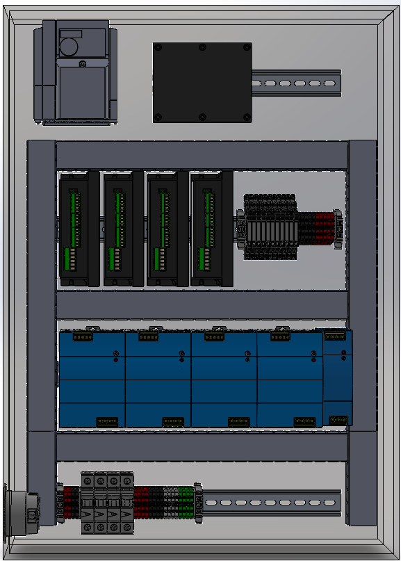
Hey All! First post here. I've built a few plasma tables before, but I'm converting my first mill over. Its an old lagun knee mill, I hadn't done all the research before I started buying components because I figured it couldn't be that much different from a plasma table but here we are and I bought closed loop steppers but wish I would've gone servos.
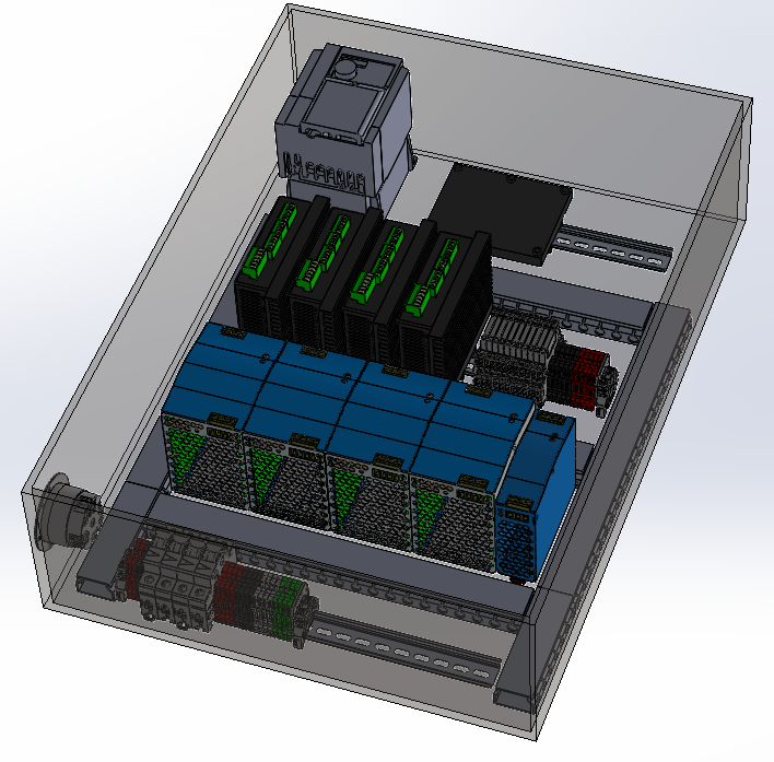
But on to the actual point, I'm trying to build this box out really nice this time around, and am trying to plan it all as best I can before I start mounting and moving stuff 10 times. I was hoping some of you with some experience might chime in and tell me if something I am doing is either just not going to work, or not optimal.
Here's my list of parts:
VFD: Mitsubishi D700
Controller: Mesa 7i96S
Stepper Drivers: CL86T Closed Loop Drivers (Stepper online)
Steppers: Nema 34 12 Nm
Din Relays (10) For eventual accessories (mist, air burst, power draw bar)
Power Supplies: 4 - 48v, 1 - 12v, 1 -5v
Breakers: 1 - 30 amp, 1 - 20 amp
The Mesa card will be up on the top row, leaving room for a daughterboard later if needed/wanted
I figured pneumatics should go in a second box to isolate in case of water.
Only thing I'm really concerned about is if the VFD is ok to be that close to my controller. Not sure if it'll cause any RF interference or anything.
Thanks for any advice!
Attachments:
Please Log in or Create an account to join the conversation.
- spumco
- Offline
- Platinum Member
-

Less
More
- Posts: 1974
- Thank you received: 808
16 Oct 2024 22:42 #312310
by spumco
Replied by spumco on topic Control Box Design
Power supplies & VFD up top
Then drives
Then controller and field IO at bottom. Field IO cables exit through bottom of case with drip-legs. Saves running lots of conductors all the way across the panel.
Vent the top of the enclosure if possible (i.e. add a chip/splash guard over the vent), or the top of the door if not possible.
Fans at bottom or top (intake or exhaust opposite fans).
I prefer a positive pressure airflow (fans at bottom) rather than negative-pressure, but that's splitting hairs.
Basically - heat-producing parts at top, controller and sensitive IO as far away from VFD's and noisy servos as possible.
And if you haven't bought them yet, I'd suggest using a big toroidal PS for the steppers rather than a bunch of switching supplies.
Please Log in or Create an account to join the conversation.
- Vair8
- Offline
- New Member
-

Less
More
- Posts: 5
- Thank you received: 0
16 Oct 2024 23:08 #312312
by Vair8
Replied by Vair8 on topic Control Box Design
Good point on hot stuff up top. I’ll definitely be switching that up! So far I’ve only got the one power supply that was left over from another project, so I’m not opposed to switching them out at all.
Please Log in or Create an account to join the conversation.
- tommylight
-

- Away
- Moderator
-

Less
More
- Posts: 21276
- Thank you received: 7265
16 Oct 2024 23:26 #312314
by tommylight
Replied by tommylight on topic Control Box Design
How many amps does the power supply have?
If the picture is anything to go by size vise, 2 should be enough, maybe, just maybe 1 ...
If the picture is anything to go by size vise, 2 should be enough, maybe, just maybe 1 ...
Please Log in or Create an account to join the conversation.
- Vair8
- Offline
- New Member
-

Less
More
- Posts: 5
- Thank you received: 0
17 Oct 2024 00:01 #312315
by Vair8
Replied by Vair8 on topic Control Box Design
Current power supply is a 48v 10 amp meanwell.
Here’s the motor and drivers I currently have.
12 Nm Stepper Online
Just a quick search for toroidal supplies, my driver is rated for 80v, I could possibly do a single 72v supply like this one.
1440W 72V
Here’s the motor and drivers I currently have.
12 Nm Stepper Online
Just a quick search for toroidal supplies, my driver is rated for 80v, I could possibly do a single 72v supply like this one.
1440W 72V
Please Log in or Create an account to join the conversation.
- Benb
-

- Offline
- Elite Member
-

Less
More
- Posts: 183
- Thank you received: 60
17 Oct 2024 01:22 #312320
by Benb
Replied by Benb on topic Control Box Design
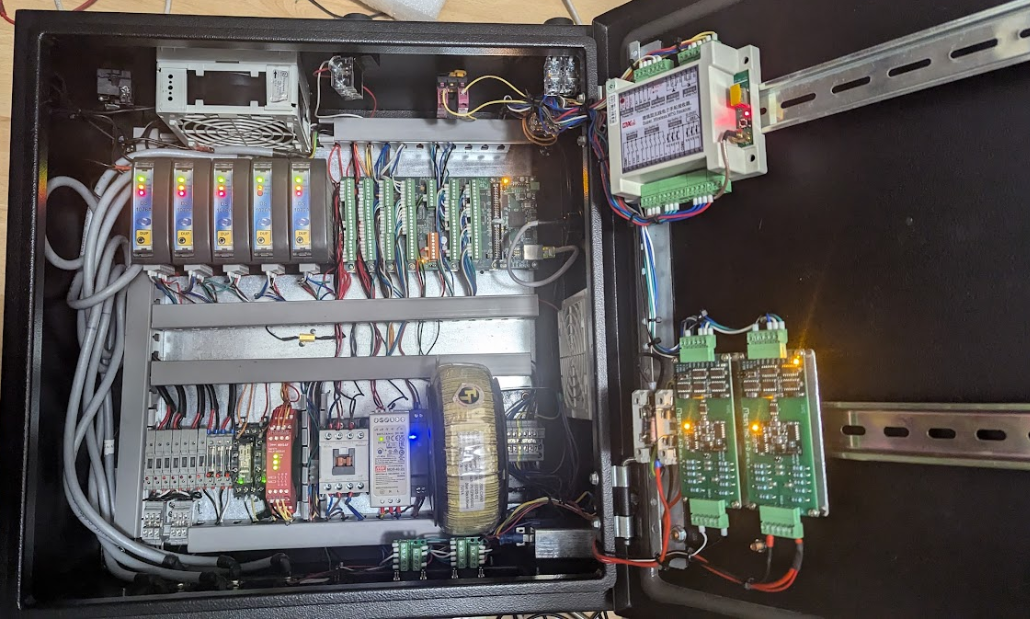
The left wire duct should be twice as large as the others, since it will have bunch of cable going through it from the bottom of the panel to the stepper drives. You will also need room for relays for those heavy loads. It is better to have extra space in the panel. We usually add 10% for unseen. The example below is pictue of control panel that shows a spider nest of cables hanging on the left. Also, the 1inch or 1.5” wire ducts are too small, they look cut but not practical.However, I like the way the toroidal transformer is mounted.
Attachments:
Please Log in or Create an account to join the conversation.
- spumco
- Offline
- Platinum Member
-

Less
More
- Posts: 1974
- Thank you received: 808
17 Oct 2024 01:38 #312321
by spumco
Your drives can take 110VDC, or 80VAC. Antek has toroid transformers or complete toiroid PSU's with rectifiers and caps.
I'd suggest running as close to the max voltage your drives will permit - this will give you better performance at higher RPM.
A simple toroid will be easier to mount (see @Benb's post) than a complete PSU, and be cheaper, too. Just be sure to check your supply voltage... in my case I'm averaging 240-245VAC, and my "100VDC" PSU from Antek is actually putting out ~104VDC. Pretty close to my drive max.
So if you get a 78V toroid and your supply voltage is on the high side, you might over-volt your 80V drives.
I didn't see any contactors or other power-handling components (fuses, breakers, etc.) in your layout. Are you planning to just use the main disconnect switch as your 'off' control? Yank the plug out of the wall 'estop'?
Do you have a way to start LCNC, your controller, and IO without powering up your VFD and stepper drives?
Print out a page with your components and use a crayon or pen to draw the conductor/cable paths through everything.
VAC-IN -> disconnect -> beakers/fuses -> distribution block -> contactor(s) -> VFD & stepper PSU/transformer & 24vdc/5vdc PSU's for IO & controller
Replied by spumco on topic Control Box Design
Current power supply is a 48v 10 amp meanwell.
Here’s the motor and drivers I currently have.
12 Nm Stepper Online
Just a quick search for toroidal supplies, my driver is rated for 80v, I could possibly do a single 72v supply like this one.
1440W 72V
Your drives can take 110VDC, or 80VAC. Antek has toroid transformers or complete toiroid PSU's with rectifiers and caps.
I'd suggest running as close to the max voltage your drives will permit - this will give you better performance at higher RPM.
A simple toroid will be easier to mount (see @Benb's post) than a complete PSU, and be cheaper, too. Just be sure to check your supply voltage... in my case I'm averaging 240-245VAC, and my "100VDC" PSU from Antek is actually putting out ~104VDC. Pretty close to my drive max.
So if you get a 78V toroid and your supply voltage is on the high side, you might over-volt your 80V drives.
I didn't see any contactors or other power-handling components (fuses, breakers, etc.) in your layout. Are you planning to just use the main disconnect switch as your 'off' control? Yank the plug out of the wall 'estop'?
Do you have a way to start LCNC, your controller, and IO without powering up your VFD and stepper drives?
Print out a page with your components and use a crayon or pen to draw the conductor/cable paths through everything.
VAC-IN -> disconnect -> beakers/fuses -> distribution block -> contactor(s) -> VFD & stepper PSU/transformer & 24vdc/5vdc PSU's for IO & controller
Please Log in or Create an account to join the conversation.
- Vair8
- Offline
- New Member
-

Less
More
- Posts: 5
- Thank you received: 0
17 Oct 2024 02:03 #312322
by Vair8
Replied by Vair8 on topic Control Box Design
Good point! I do have a handful of 40 amp solid state relays I didnt draw in there yet that I plan on adding for powering on and off along with a couple of switches. had a solidworks update but I'll redraw some stuff and post it again!
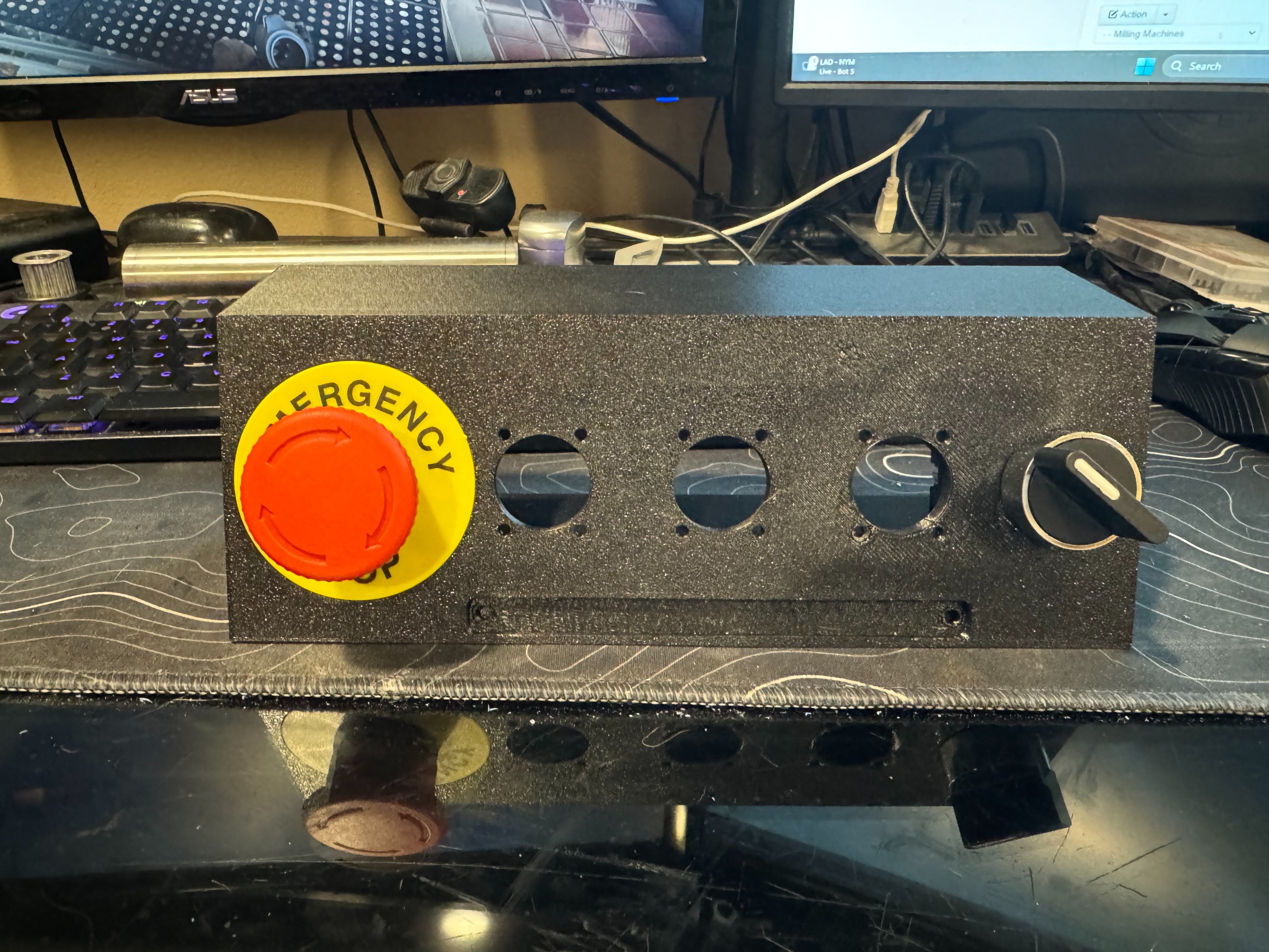
This panel will probably be behind the mill and I'll make a separate control panel where my computer sits that will have e-stop and the other goodies. Possibly something similar to this 3d printed estop switch combo that I made for a rocket thrust stand.
Seriously thank you all for the suggestions! always good to get another viewpoint!
Attachments:
Please Log in or Create an account to join the conversation.
- spumco
- Offline
- Platinum Member
-

Less
More
- Posts: 1974
- Thank you received: 808
17 Oct 2024 02:21 #312323
by spumco
Replied by spumco on topic Control Box Design
I like SSR's, but I don't trust them as main disconnect (i.e. Estop) devices. SSR's tend to fail closed, not open. Even if you don't use a dedicated, guided-contact estop relay, a magnetic contactor between your overcurrent protection device(s) and everything else is a safe bet.
Final suggestion - draw your wiring diagram before you settle on a control panel layout. It will help you internalize what voltages go where so your layout makes sense.
Plenty of times I've had to add a relay, or stuff some un-accounted-for component because I hadn't finalized the wiring. Or run out of field connectors for IO, or other dumb stuff - like switching from steppers to servos in the middle of a build.
Please Log in or Create an account to join the conversation.
- Vair8
- Offline
- New Member
-

Less
More
- Posts: 5
- Thank you received: 0
17 Oct 2024 06:18 #312339
by Vair8
Replied by Vair8 on topic Control Box Design
Good advice on the SSR's and the diagram, I'll do that. Also on the note of switching from steppers to servos.... I only have 2 of my motors so far, do you think I'll regret not just starting with servos? its not too late to return at least 1 of them.
The machine already had a bunch of glentek stuff on it, but it was all oldschool analog and I wanted to modernize and I just impulse bought the biggest steppers I could find.
The machine already had a bunch of glentek stuff on it, but it was all oldschool analog and I wanted to modernize and I just impulse bought the biggest steppers I could find.
Please Log in or Create an account to join the conversation.
Moderators: piasdom
Time to create page: 0.244 seconds


