Remora - ethernet NVEM / EC300 / EC500 cnc board
- scotta
-
 Topic Author
- Offline
- Platinum Member
-

Less
More
- Posts: 959
- Thank you received: 489
15 Jan 2022 03:36 - 15 Jan 2022 03:56 #231850
by scotta
Remora - ethernet NVEM / EC300 / EC500 cnc board was created by scotta
With Remora firmware now running on STM32 F4 and F1 series MCU's and ethernet communications working in a proof of concept using a w5500 interface. The next logical step is to develop native ethernet functionality.
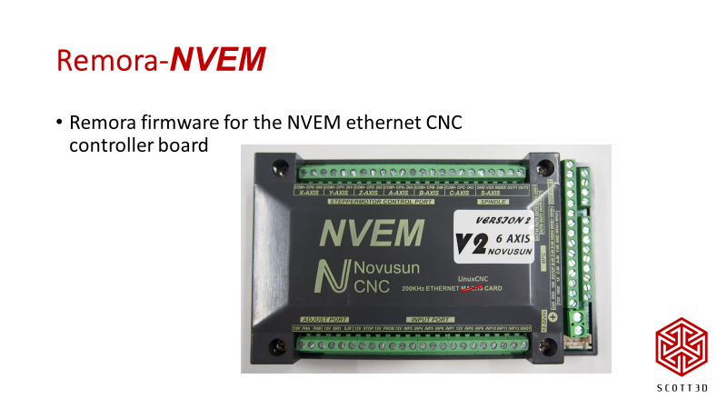
There aren't many ethernet enable STM32 3D printer controller boards around but I came across the NVEM ethernet board for Mach3. It has an STM32F207 on board so expanding Remora to this board seems feasible.
I thought it would be fun to document my attempts to get Remora (with ethernet) up and running on this board. Also to give some hints on how I've tackled this on other boards.
This board also has opto isolated input and outputs and level shifting on the step and direction outputs. So a more "industrial" board suitable for normal CNC machines where a 3D printer controller board is not seen to be a suitable option.
Attachments:
Last edit: 15 Jan 2022 03:56 by scotta.
Please Log in or Create an account to join the conversation.
- scotta
-
Topic Author
- Offline
- Platinum Member
-
Less
More
- Posts: 959
- Thank you received: 489
15 Jan 2022 03:40 #231851
by scotta
Replied by scotta on topic Remora - ethernet NVEM / EC300 / EC500 cnc board
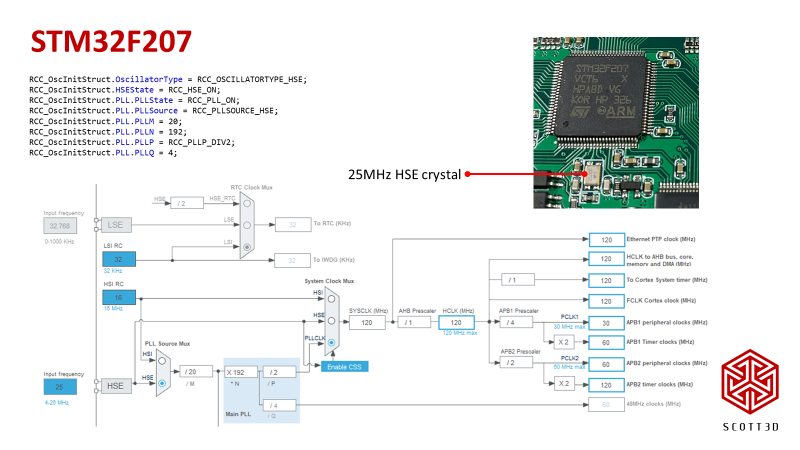
The first step with any controller board is to get a simple "Hello World" up and running so that we have a working system configuration as a basis. Before diving into creating an MBed target, it's more straight forward to use STMCubeIDE initially. The NVEM board has no bootloader so no hassles with changing starting addresses.
The board has a 25MHz HSE crystal.
The board has a 25MHz HSE crystal.
Attachments:
Please Log in or Create an account to join the conversation.
- scotta
-
Topic Author
- Offline
- Platinum Member
-
Less
More
- Posts: 959
- Thank you received: 489
15 Jan 2022 03:42 #231852
by scotta
Replied by scotta on topic Remora - ethernet NVEM / EC300 / EC500 cnc board
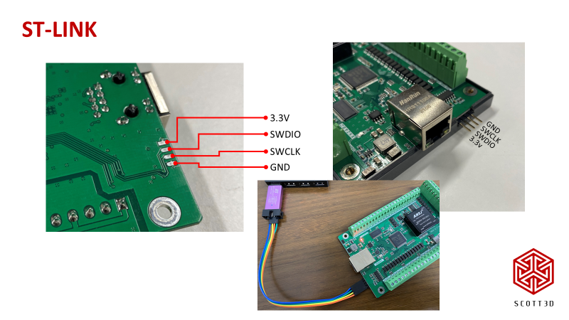
On the back of the board is the programming pads used in the factory. Some tracking of traces resulted in a usable ST-LINK interface.
Attachments:
The following user(s) said Thank You: tivoi
Please Log in or Create an account to join the conversation.
- scotta
-
Topic Author
- Offline
- Platinum Member
-
Less
More
- Posts: 959
- Thank you received: 489
15 Jan 2022 03:50 #231853
by scotta
Replied by scotta on topic Remora - ethernet NVEM / EC300 / EC500 cnc board
For a "Hello World" it's easy if the board as an onboard LED that we can blink. Unfortunately no such luck with the NVEM board. A serial output will have to do. The board has two RS232 ports, one on the screw terminal and another on the other on the XH header.
These are true RS232 driven by a MAX3232 inverting transceiver giving protection to the STM32 UARTs, but this also means a RS232 to USB serial adaptor is needed rather than a TTL type that is used for direction connection to the MCU UART.

These are true RS232 driven by a MAX3232 inverting transceiver giving protection to the STM32 UARTs, but this also means a RS232 to USB serial adaptor is needed rather than a TTL type that is used for direction connection to the MCU UART.
Attachments:
Please Log in or Create an account to join the conversation.
- scotta
-
Topic Author
- Offline
- Platinum Member
-
Less
More
- Posts: 959
- Thank you received: 489
15 Jan 2022 03:53 #231854
by scotta
Replied by scotta on topic Remora - ethernet NVEM / EC300 / EC500 cnc board
So after digging through the odds and ends, I found an RS232 adaptor from back when I was developing the Huanyang VSD component. First STMCube setup worked with data streaming out of UART2, the XH header.

Attachments:
The following user(s) said Thank You: tommylight
Please Log in or Create an account to join the conversation.
- ALittleOffTheRails
-

- Visitor
-

15 Jan 2022 08:04 #231872
by ALittleOffTheRails
Replied by ALittleOffTheRails on topic Remora - ethernet NVEM / EC300 / EC500 cnc board
I think MX_Master may have looked into this before, but it seemed how some of the pins were utilized didn't make much sense, so he didn't pursue it further.
Lets see how you go mate.
Lets see how you go mate.
Please Log in or Create an account to join the conversation.
- scotta
-
Topic Author
- Offline
- Platinum Member
-
Less
More
- Posts: 959
- Thank you received: 489
15 Jan 2022 20:08 #231916
by scotta
The very new bit for me is the ethernet side of things. This will be the next challenge..
Replied by scotta on topic Remora - ethernet NVEM / EC300 / EC500 cnc board
Remora does not rely on hardware timers that have limited pin connectivity, so I think there is a very good chance of getting it running. I'm very suspicious that the original NVEM firmware uses DDS based step generators just like Remora.I think MX_Master may have looked into this before, but it seemed how some of the pins were utilized didn't make much sense, so he didn't pursue it further.
Lets see how you go mate.
The very new bit for me is the ethernet side of things. This will be the next challenge..
Please Log in or Create an account to join the conversation.
- Aaroncnc
- Offline
- Elite Member
-

Less
More
- Posts: 204
- Thank you received: 45
15 Jan 2022 20:20 #231918
by Aaroncnc
Replied by Aaroncnc on topic Remora - ethernet NVEM / EC300 / EC500 cnc board
this is exciting to watch.
I bought a w5500 for use on my boards incase i decide to not use a rpi4.
But one question.
If on the above board nothing is hardware based and all in software will this be a problem for high speed encoders?
I understand not everyone has a need for one and could get away with lower resolution to track something simple like a spindle. ie not using a 300ppr quad encoder and going for closer to 80-100ppr.
Please Log in or Create an account to join the conversation.
- scotta
-
Topic Author
- Offline
- Platinum Member
-
Less
More
- Posts: 959
- Thank you received: 489
15 Jan 2022 20:40 #231923
by scotta
Replied by scotta on topic Remora - ethernet NVEM / EC300 / EC500 cnc board
Hi Aaron,
You might be in luck. It looks like the adjust port is setup as an encoder input and the pins used can be connected to TIMER 4, so the Remora hardware QEI module can be assigned to this. This will give at least one high speed encoder input.
The inputs are opto isolated, not sure if this will limit the max frequency.
I'll need to trace out the other inputs to see if others can be used for QEI as well.
This would raise another question around the default configuration of the board as it does not have an SD card, the config will need to be hard coded. Well at least initially. There is an unmarked IC on the board which I'm suspicious is an EEPROM.
Please Log in or Create an account to join the conversation.
- Aaroncnc
- Offline
- Elite Member
-
Less
More
- Posts: 204
- Thank you received: 45
15 Jan 2022 21:00 - 15 Jan 2022 21:01 #231930
by Aaroncnc
Replied by Aaroncnc on topic Remora - ethernet NVEM / EC300 / EC500 cnc board
Hmm think it would be possible to send a config over ethernet?
so you would have a config file located in your linuxcnc config folder then sets the values.
But i think for getting off the ground fast just setting it for most other peoples use case would be better.
I myself do have a few st-links in a drawer somewhere if i needed to make changes.
Whats the part number on the optos?
Last edit: 15 Jan 2022 21:01 by Aaroncnc.
Please Log in or Create an account to join the conversation.
Time to create page: 2.639 seconds