Remora - ethernet NVEM / EC300 / EC500 cnc board
- scotta
-
 Topic Author
- Offline
- Platinum Member
-

Less
More
- Posts: 957
- Thank you received: 486
21 Sep 2023 21:48 #281335
by scotta
Replied by scotta on topic Remora - ethernet NVEM / EC300 / EC500 cnc board
No need to use tftp command line to upload the config file. Just use the python script. It will check that it is proper JSON and add the required header meta data before doing the tftp upload.
If your config file is called config.txt, then your command would be
python3 upload_config.py config.txt
If your config file is called config.txt, then your command would be
python3 upload_config.py config.txt
Please Log in or Create an account to join the conversation.
- cnc-phil
- Offline
- New Member
-

Less
More
- Posts: 11
- Thank you received: 2
22 Sep 2023 06:36 - 22 Sep 2023 06:38 #281349
by cnc-phil
Replied by cnc-phil on topic Remora - ethernet NVEM / EC300 / EC500 cnc board
@
aaamil13
I don't know if it should work. But why port 69? Passive FTP is on 21, AFAIK.
I don't know if it should work. But why port 69? Passive FTP is on 21, AFAIK.
Last edit: 22 Sep 2023 06:38 by cnc-phil.
Please Log in or Create an account to join the conversation.
- aaamil13
- Offline
- New Member
-
Less
More
- Posts: 10
- Thank you received: 1
22 Sep 2023 14:47 - 22 Sep 2023 15:11 #281385
by aaamil13
Replied by aaamil13 on topic Remora - ethernet NVEM / EC300 / EC500 cnc board
open("/tmp/config.txt", "wb").write(config)
# Upload using TFTP, set large timeout
client = tftpy.TftpClient("10.10.10.10", 69)
client.upload("config", "/tmp/config.txt", timeout=30)
It's a TFTP which differs from FTP and TFTP is configured on port 69.
I have no steps forward, PyOCD communication is timed out, and even no debug info on ComPort. Flashed with remora-rt1052-1.1.0.bin and remora-rt1052-1.0.0.bin. Flash is OK, have ping to 10.10.10.10, but not able to upload configuration file and no ComPort. LinuxCNC communicates with EC500v5, I am able to Enable and start the board from LinuxCNC, but if i try to move Axis then popup "joint 0 following error". BOOT led sets on when i press enable on LinuxCNC.
I am not sure if debug ComPort is DB9 port on EC500 or have to use some other pins.
Do I have to enable TFTP by a special procedure ( short pin, some command or etc.) and is there a procedure to enable debug on ComPort
Thanks in advance
Last edit: 22 Sep 2023 15:11 by aaamil13.
Please Log in or Create an account to join the conversation.
- cnc-phil
- Offline
- New Member
-
Less
More
- Posts: 11
- Thank you received: 2
22 Sep 2023 15:23 - 22 Sep 2023 15:42 #281388
by cnc-phil
Replied by cnc-phil on topic Remora - ethernet NVEM / EC300 / EC500 cnc board
@aaamil13
You are right wtih the 69 port. I do not have a ec500 controller. But on the nvem controller the file is uploaded with the command scotta posted above and then it gets automatically restarted, I think this should be the same for your controller, otherwise scotta would have mentioned it in the post.
With the nvem controller the config upload uses the same pins as the firmware upload. Have you tried scotta`s command to upload, maybe the ftp server on the ec500 does not support the put command? (The python script does more, it adds some kind of checksum and padding and so on). For the joint0 following error, there was info same pages ago. (I got rid of it with the motor setup/config menu in the axis menu (can not check right now, I had to raise the second value), but maybe the last info is complete nonsense (using cheap nema23 steppers)).
Last edit: 22 Sep 2023 15:42 by cnc-phil.
Please Log in or Create an account to join the conversation.
- aaamil13
- Offline
- New Member
-
Less
More
- Posts: 10
- Thank you received: 1
22 Sep 2023 19:15 - 31 Aug 2024 19:59 #281410
by aaamil13
Replied by aaamil13 on topic Remora - ethernet NVEM / EC300 / EC500 cnc board
Finally got some success with ComPort. Debug port is the one with type DB9 on the board,
Pin 1 -> +5V
Pin 2 -> RXD
Pin 3 -> TXD
Pin 5 -> GND
But the levels are not RS232. these are 5V TTL logic levels.
I have some kind of data but it is not readable for now.
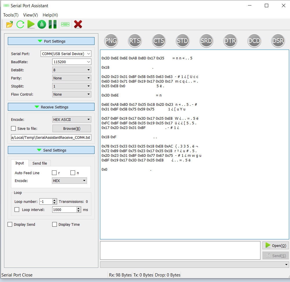
Baud ->115200, Parity -no, DataBits - 8 , StopBits 1,
Firmware -> remora-rt1052-1.0.0.bin
Board EC500v5
When i try to Upload my config.txt there is some text on Debug port, but unfortunately can't read it.
EC500 has RS232 voltage levels, Pin 3 is TX and should be connected to PIN 2 on the computer side . Baud ->115200, Parity -no, Data Bits - 8 , Stop Bits 1.
Pin 2 -> RXD
Pin 3 -> TXD
Pin 5 -> GND
But the levels are not RS232. these are 5V TTL logic levels.
I have some kind of data but it is not readable for now.
Baud ->115200, Parity -no, DataBits - 8 , StopBits 1,
Firmware -> remora-rt1052-1.0.0.bin
Board EC500v5
When i try to Upload my config.txt there is some text on Debug port, but unfortunately can't read it.
EC500 has RS232 voltage levels, Pin 3 is TX and should be connected to PIN 2 on the computer side . Baud ->115200, Parity -no, Data Bits - 8 , Stop Bits 1.
Last edit: 31 Aug 2024 19:59 by aaamil13.
Please Log in or Create an account to join the conversation.
- scotta
-
Topic Author
- Offline
- Platinum Member
-
Less
More
- Posts: 957
- Thank you received: 486
22 Sep 2023 22:10 #281414
by scotta
Replied by scotta on topic Remora - ethernet NVEM / EC300 / EC500 cnc board
The latest firmware is v1.1.0, but this only added encoder support.
I'd try ascii encoding setting on your receive to see if that helps.
For the TFTP, are you going through a router or direct connection between computer and controller board?
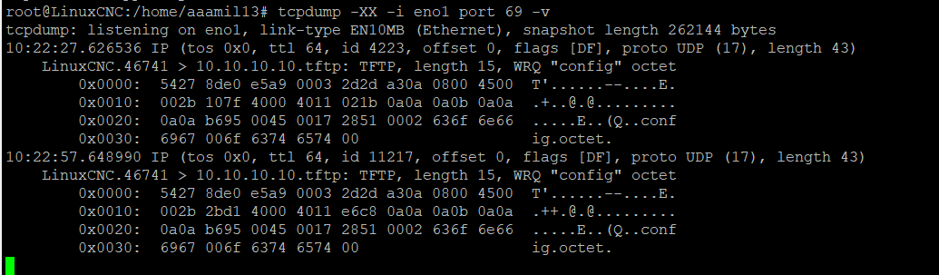
Have you tried monitoring the eth0 with wireshark to see if any response packets are coming from the board?
During the TFTP transfer, the controller board threads are stopped. If the upload fails you would still need to power cycle the board to get everything back and running. On a successful upload this happens with a software reset of the board.
I'd try ascii encoding setting on your receive to see if that helps.
For the TFTP, are you going through a router or direct connection between computer and controller board?
Have you tried monitoring the eth0 with wireshark to see if any response packets are coming from the board?
During the TFTP transfer, the controller board threads are stopped. If the upload fails you would still need to power cycle the board to get everything back and running. On a successful upload this happens with a software reset of the board.
Please Log in or Create an account to join the conversation.
- oficinerobotica
-

- Offline
- Senior Member
-

Less
More
- Posts: 47
- Thank you received: 12
23 Sep 2023 04:58 #281432
by oficinerobotica
Replied by oficinerobotica on topic Remora - ethernet NVEM / EC300 / EC500 cnc board
First of all I just don't know how I can thank enough you guys for the tremendous work. I love mesa cards just like anybody else here but given the availability and cost to importing them in certain parts of the world, blowing one like I did can become a costly mistake.
I just received my ec500 card but I don't know how to identify what version it is.
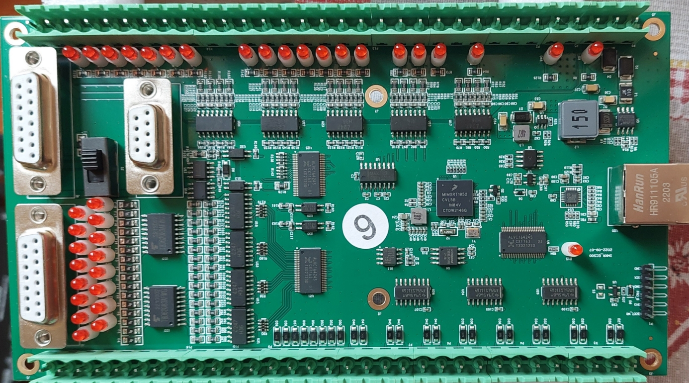
I would like to flash it using a Pi Pico using this instructables "cmsis-dap-v2" programmer as i understand that it could be the easiest way to do it afterall. www.instructables.com/CMSIS-DAP-V2-Progr...With-Raspberry-Pi-P/
Can somebody please help me with the connection between the pi and the ec500? I'vd read the whole thread twice and watched Scotta's videos but it is still not clear to me.
P.S. @scotta .... where can I donate?
I just received my ec500 card but I don't know how to identify what version it is.
I would like to flash it using a Pi Pico using this instructables "cmsis-dap-v2" programmer as i understand that it could be the easiest way to do it afterall. www.instructables.com/CMSIS-DAP-V2-Progr...With-Raspberry-Pi-P/
Can somebody please help me with the connection between the pi and the ec500? I'vd read the whole thread twice and watched Scotta's videos but it is still not clear to me.
P.S. @scotta .... where can I donate?
Attachments:
Please Log in or Create an account to join the conversation.
- aaamil13
- Offline
- New Member
-
Less
More
- Posts: 10
- Thank you received: 1
23 Sep 2023 07:34 - 23 Sep 2023 08:04 #281442
by aaamil13
Replied by aaamil13 on topic Remora - ethernet NVEM / EC300 / EC500 cnc board
There is no big difference in comPort debug responce when encode UTF or ASCII. And no answer from EC500v5 on TFTP port. I have direct connection to the EC500v5 with the cable delivered with the board.
And transfer LinuxCNC<->EC500 when Enabled
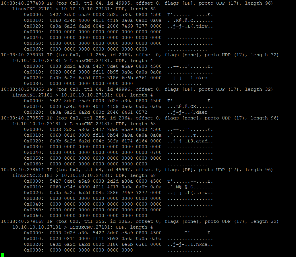
And transfer LinuxCNC<->EC500 when Enabled
Attachments:
Last edit: 23 Sep 2023 08:04 by aaamil13.
Please Log in or Create an account to join the conversation.
- aaamil13
- Offline
- New Member
-
Less
More
- Posts: 10
- Thank you received: 1
23 Sep 2023 07:59 - 23 Sep 2023 11:11 #281443
by aaamil13
Replied by aaamil13 on topic Remora - ethernet NVEM / EC300 / EC500 cnc board
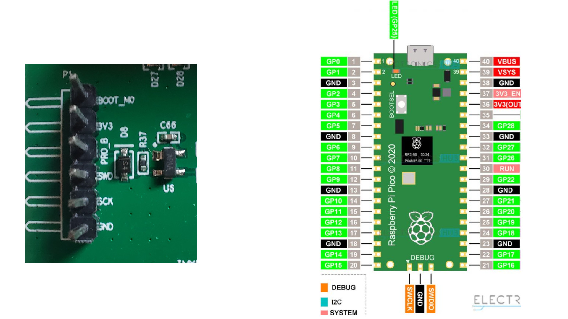
I have no experience with RPI, but you have to connect GND, SCK->SWSCK(GPIO_11), SWD->SWDIO.(PGIO_12)
If you want to use debug port, you have to connect to an adapter USB -> RS232_TTL, or you can use RX pad on the same RPI board and connect RX to DB9_Pin3 on EC500 board ( RPI_GND to DB9_5 pins too).
You must connect 24V to SYSTEM on EC500 to able to flash. If you are going to use PyOCD -> pyocd flash ./remora-rt1052-1.1.0.bin --target mimxrt1050_quadspi -v. It takes some time to flash the board. Your EC500 is V5, which uses mimxrt1052cvl5b MCU.
Last edit: 23 Sep 2023 11:11 by aaamil13.
The following user(s) said Thank You: oficinerobotica
Please Log in or Create an account to join the conversation.
- rbobey1989
-

- Offline
- Premium Member
-

Less
More
- Posts: 124
- Thank you received: 33
24 Sep 2023 20:34 - 24 Sep 2023 20:47 #281563
by rbobey1989
Replied by rbobey1989 on topic Remora - ethernet NVEM / EC300 / EC500 cnc board
Hello everyone here, I have been doing some reading about XBAR in the rt1052 refence manual (tedious), Following a comment from Scott about XBAR, to implement a Quadrature Encoder/Decoder (QDC) module it is necessary to use this module because it is not possible to map the input pads of the NVEM boards to the QDCs using IOMUX,After taking a look I have managed to understand a few things, the XBAR is a great multiplexer partly independent of IOMUX, partly because many XBAR signals coincide on inputs and outputs e.g. this house for high speed), I have done a small count of the pins mapped as inputs on the EC500 and due to the number of input pins that match XBAR, up to 2 encoders could be connected, I have used part of the C remora version file -rt1052 for counting:
#define IN01_PORT GPIO3 //GPIO_EMC_39/**/Impossible Mux
#define IN01_PIN 25
#define IN02_PORT GPIO4 //GPIO_EMC_13/**/XBAR1_IN25
#define IN02_PIN 13
#define IN03_PORT GPIO4 //GPIO_EMC_14/**/XBAR1_INOUT19
#define IN03_PIN 14
#define IN04_PORT GPIO3 //GPIO_EMC_38/**/Impossible Mux
#define IN04_PIN 24
#define IN05_PORT GPIO3 //GPIO_EMC_32/**/Impossible Mux
#define IN05_PIN 18
#define IN06_PORT GPIO4 //GPIO_EMC_31/**/Impossible Mux
#define IN06_PIN 31
#define IN07_PORT GPIO4 //GPIO_EMC_27/**/Impossible Mux
#define IN07_PIN 27
#define IN08_PORT GPIO3 //GPIO_EMC_35/**/XBAR1_INOUT18
#define IN08_PIN 21
#define IN09_PORT GPIO3 //GPIO_EMC_33/**/Impossible Mux
#define IN09_PIN 19
#define IN10_PORT GPIO3 //GPIO_EMC_34/**/Impossible Mux
#define IN10_PIN 20
#define IN11_PORT GPIO4 //GPIO_EMC_00/**/XBAR1_IN02
#define IN11_PIN 0
#define IN12_PORT GPIO3 //GPIO_EMC_37/**/XBAR1_IN23
#define IN12_PIN 23
#define IN13_PORT GPIO4 //GPIO_EMC_28/**/Impossible Mux
#define IN13_PIN 28
#define IN14_PORT GPIO4 //GPIO_EMC_15/**/XBAR1_IN20
#define IN14_PIN 15
#define IN15_PORT GPIO4 //GPIO_EMC_25/**/Impossible Mux
#define IN15_PIN 25
#define IN16_PORT GPIO4 //GPIO_EMC_09/**/Impossible Mux
#define IN16_PIN 9
There are 6 pads that can be mutiplexed using XBAR, in this case the output signals in XBAR would be those corresponding to the QDC (1 to 4).
I leave a link to the NXP forum where the above is mentioned, I hope it helps, greetings
Last edit: 24 Sep 2023 20:47 by rbobey1989.
The following user(s) said Thank You: tommylight
Please Log in or Create an account to join the conversation.
Time to create page: 1.217 seconds