Remora - ethernet NVEM / EC300 / EC500 cnc board
- CBollweg
-

- Visitor
-

19 Sep 2022 20:09 #252362
by CBollweg
Replied by CBollweg on topic Remora - ethernet NVEM / EC300 / EC500 cnc board
I have now set up Linuxcnc again. Still, Linuxcnc works until a key is pressed on the NVMPG. I started linuxcnc from the terminal and it says the ethernet connection was lost. Once the EC500 has been de-energized and energized again, Linuxcnc continues to run without any problems until a key is pressed on the NWMPG. So the NVMPG seems to be interfering with the Ethernet connection.
Hi Christian, sounds like the behaviour of the earlier firmware. I've cleaned up my Github so that only the latest tested firmware is there. I've tested this firmware with my NVMPG and it's working as expected.
github.com/scottalford75/Remora-EC500/bl...C500-STM32-1.0.0.hex
Hi Scott,
You are my hero. With the new firmware everything works as it should. Terrific. Now it can go on. Thank you very much for your work, your development and your support
Can you confirm iff the 0-10 volt is working?
Hi Scott, i will Check, but IT will Take some time. Bei Back top Test next week
Please Log in or Create an account to join the conversation.
- CBollweg
-
- Visitor
-
20 Sep 2022 14:03 #252402
by CBollweg
I checked the PWM signal today. Apparently it doesn't work. I connected a 9volt block battery to Gnd and Vso and measured in Com. Everything is displayed correctly in the Hal Show, however, the measured value between Vso and Com does not change. It is constantly at 8.7 volts. Is my measurement method correct?
Replied by CBollweg on topic Remora - ethernet NVEM / EC300 / EC500 cnc board
Hi Scott,Great to hear that you are up and running. Does your board look like mine or the "newer" version with the PWM to analogue chip? If it has the chip then the 0 - 10V should also work as it's using the same code as the NVEM.
I checked the PWM signal today. Apparently it doesn't work. I connected a 9volt block battery to Gnd and Vso and measured in Com. Everything is displayed correctly in the Hal Show, however, the measured value between Vso and Com does not change. It is constantly at 8.7 volts. Is my measurement method correct?
Please Log in or Create an account to join the conversation.
- Aanvragen0903
- Offline
- New Member
-

Less
More
- Posts: 11
- Thank you received: 3
20 Sep 2022 16:44 #252414
by Aanvragen0903
You must connect 24Volt to the controller Main Power Port and the Output Power Port
Connect an Voltmeter at the COM and VSO of the Spindle port.
Give an command in Linuxcnc to run the Spindle and change the speed with a command. Look at the voltmeter if it changes.
Replied by Aanvragen0903 on topic Remora - ethernet NVEM / EC300 / EC500 cnc board
Your method is not correct.
Great to hear that you are up and running. Does your board look like mine or the "newer" version with the PWM to analogue chip? If it has the chip then the 0 - 10V should also work as it's using the same code as the NVEM.
Hi Scott,
I checked the PWM signal today. Apparently it doesn't work. I connected a 9volt block battery to Gnd and Vso and measured in Com. Everything is displayed correctly in the Hal Show, however, the measured value between Vso and Com does not change. It is constantly at 8.7 volts. Is my measurement method correct?
You must connect 24Volt to the controller Main Power Port and the Output Power Port
Connect an Voltmeter at the COM and VSO of the Spindle port.
Give an command in Linuxcnc to run the Spindle and change the speed with a command. Look at the voltmeter if it changes.
Please Log in or Create an account to join the conversation.
- CBollweg
-
- Visitor
-
21 Sep 2022 06:16 - 21 Sep 2022 06:19 #252478
by CBollweg
Replied by CBollweg on topic Remora - ethernet NVEM / EC300 / EC500 cnc board
Great to hear that you are up and running. Does your board look like mine or the "newer" version with the PWM to analogue chip? If it has the chip then the 0 - 10V should also work as it's using the same code as the NVEM.
Hi Scott,
I checked the PWM signal today. Apparently it doesn't work. I connected a 9volt block battery to Gnd and Vso and measured in Com. Everything is displayed correctly in the Hal Show, however, the measured value between Vso and Com does not change. It is constantly at 8.7 volts. Is my measurement method correct?
Your method is not correct.
You must connect 24Volt to the controller Main Power Port and the Output Power Port
Connect an Voltmeter at the COM and VSO of the Spindle port.
Give an command in Linuxcnc to run the Spindle and change the speed with a command. Look at the voltmeter if it changes.
Hi Scott,
I have connected 24 volts to the board and for the IOs. Likewise at the General Output Interface (Pin 1+5). I don't see any voltage on the VSO and Com. Regardless of the speed set in Linuxcnc.
Last edit: 21 Sep 2022 06:19 by CBollweg.
Please Log in or Create an account to join the conversation.
- Aanvragen0903
- Offline
- New Member
-
Less
More
- Posts: 11
- Thank you received: 3
21 Sep 2022 07:35 - 21 Sep 2022 07:36 #252483
by Aanvragen0903
Replied by Aanvragen0903 on topic Remora - ethernet NVEM / EC300 / EC500 cnc board
Did you gave the M3 (Spindle CW) command and de S command in LinuxCNC?
Like S1000 or S750 or.......
You don't have to connect 24 Volt to the general Output. See manual EC500
Iff you have a voltmeter between COM and VSO and you have started the spindle (M3) and then change the rpm of the spindle with the S command the reading of the voltmeter (DC) should change
Like S1000 or S750 or.......
You don't have to connect 24 Volt to the general Output. See manual EC500
Iff you have a voltmeter between COM and VSO and you have started the spindle (M3) and then change the rpm of the spindle with the S command the reading of the voltmeter (DC) should change
Last edit: 21 Sep 2022 07:36 by Aanvragen0903.
Please Log in or Create an account to join the conversation.
- CBollweg
-
- Visitor
-
21 Sep 2022 10:18 #252493
by CBollweg
Hi Scott,
here is a short video of what i did. photos.app.goo.gl/7iqFXFaowZrbVXis6 (hope it works)
Replied by CBollweg on topic Remora - ethernet NVEM / EC300 / EC500 cnc board
Did you gave the M3 (Spindle CW) command and de S command in LinuxCNC?
Like S1000 or S750 or.......
You don't have to connect 24 Volt to the general Output. See manual EC500
Iff you have a voltmeter between COM and VSO and you have started the spindle (M3) and then change the rpm of the spindle with the S command the reading of the voltmeter (DC) should change
Hi Scott,
here is a short video of what i did. photos.app.goo.gl/7iqFXFaowZrbVXis6 (hope it works)
Please Log in or Create an account to join the conversation.
- Aanvragen0903
- Offline
- New Member
-
Less
More
- Posts: 11
- Thank you received: 3
21 Sep 2022 18:57 #252530
by Aanvragen0903
Replied by Aanvragen0903 on topic Remora - ethernet NVEM / EC300 / EC500 cnc board
Hello Christian,
Altough its difficult to see on the video, cam out of focus, looks that you give the right commands.
BTW im not Scott. Maybe he has some sugestions.
Will put Remora on my EC500 to see iff its working.
Christian are you Dutch?
Altough its difficult to see on the video, cam out of focus, looks that you give the right commands.
BTW im not Scott. Maybe he has some sugestions.
Will put Remora on my EC500 to see iff its working.
Christian are you Dutch?
Please Log in or Create an account to join the conversation.
- scotta
-
 Topic Author
- Offline
- Platinum Member
-

Less
More
- Posts: 959
- Thank you received: 489
21 Sep 2022 21:28 #252533
by scotta
Replied by scotta on topic Remora - ethernet NVEM / EC300 / EC500 cnc board
Hi the current HAL file example does not have any of the spindle commands linked to Remora outputs or SP values. You will need to test directly using halcommand and set the value of remora.SP.0 directly. And you need to have the full config loaded into the EC500.
Please Log in or Create an account to join the conversation.
- scotta
-
Topic Author
- Offline
- Platinum Member
-
Less
More
- Posts: 959
- Thank you received: 489
21 Sep 2022 21:40 #252535
by scotta
Replied by scotta on topic Remora - ethernet NVEM / EC300 / EC500 cnc board
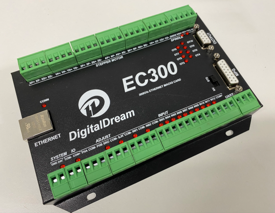
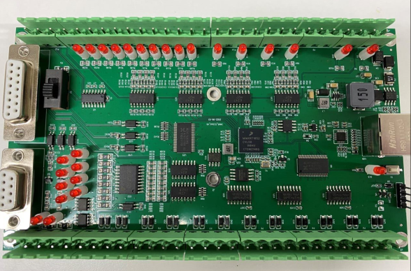
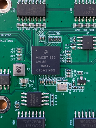
So just over two weeks from order my EC300 arrived. Like the EC500 it is quite well built and like the NVEM 2.1 has the iMX RT1052 onboard. Like the new NVEM it's using a multi layer PCB. Compared to the EC500 it is very similar except for changes to the optocouplers on the inputs and the addition of indicator LEDS for the IO.
Attachments:
The following user(s) said Thank You: MX_Master, Murphy
Please Log in or Create an account to join the conversation.
- scotta
-
Topic Author
- Offline
- Platinum Member
-
Less
More
- Posts: 959
- Thank you received: 489
21 Sep 2022 21:52 #252536
by scotta
Replied by scotta on topic Remora - ethernet NVEM / EC300 / EC500 cnc board
There is a 4 pin header and push button next to the Ethernet port. The button is connected to VCC. I was hoping that the 4 pin header was a fully exposed SWD programming port (VCC, SWDIO, SWCLK, GND), but not so. The left hand pin in the picture appears to be connected to the manual reset pin of a voltage supervisor IC.
I'm hoping the middle two pins are the SWDIO and SWCLK, the right hand pin is connected to GND. I'm thinking that due to the external flash memory and I2C EEPROM that the pin count of the RT1052 is maxed out and they are sharing IO with the SWD. Most likely using the push button on power up to change the boot sequence to make the SWD available (like the EC500). Adding this reset circuitry might allow the board to be reset with main power connected. S3 solder pads might need to be closed to connect the reset output to the MCU..?
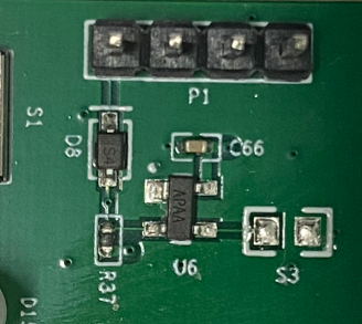
I'm hoping the middle two pins are the SWDIO and SWCLK, the right hand pin is connected to GND. I'm thinking that due to the external flash memory and I2C EEPROM that the pin count of the RT1052 is maxed out and they are sharing IO with the SWD. Most likely using the push button on power up to change the boot sequence to make the SWD available (like the EC500). Adding this reset circuitry might allow the board to be reset with main power connected. S3 solder pads might need to be closed to connect the reset output to the MCU..?
Attachments:
Please Log in or Create an account to join the conversation.
Time to create page: 0.649 seconds