Remora - ethernet NVEM / EC300 / EC500 cnc board

More
2 years 2 months ago #307588 by AlessandroEmm
thanks! I actually just come from further testing. I must have done something wrong. Because the states of the pins do actually change. Apologies.

How is it mapped now anyway, implicitly?

because on the top of the example-hal file it mentions that limit switches are configured. but i cant find them explicitly:

➜ remora-rt1052-basic cat remora-ec500.hal
# Basic HAL config file for NVEM controller board running Remora firmware
# Configured for 3 joints (A, Y, Z axes) with home and limit switches

Thanks!
Alessandro

Please Log in or Create an account to join the conversation.

More
2 years 2 months ago #307594 by cakeslob

Hi pin outputs you can find in the attachment.
Estop has 2 pins, same for probe. Other inputs have one common and one negative for each input. 

Hey, dont use this one if you have the RT1052, i dont even know how yours is still working if youve been using that one. The one you keep posting is for the STM32 version of the NVEM. use this one by raf

oK lads I have got made a thing. :)

Hope this will help somehow 
Pinout NVEM v5 RT1052 Remora firmware config pinout
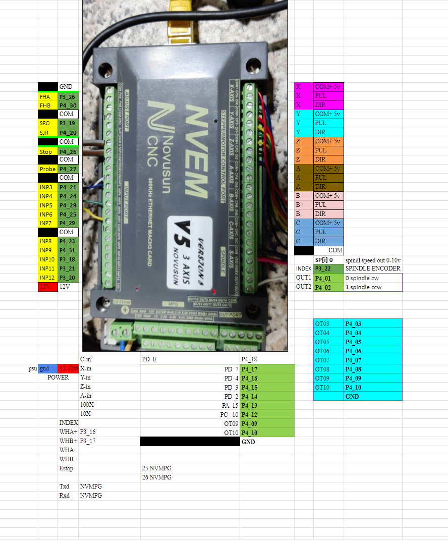
 
The following user(s) said Thank You: AlessandroEmm

Please Log in or Create an account to join the conversation.

More
2 years 2 months ago #307596 by cakeslob
Code:
{ "Thread": "Servo", "Type": "Digital Pin", "Comment": "IN03", "Pin": "P4_21", "Mode": "Input", "Data Bit": 6, "Invert": "True" },
 
"Comment": "IN03", = what its labeled as on the board
" "Pin": "P4_21"," = Physical pin assignment on the MCU
"Data Bit": 6, = Remora/HAL pin assignment
Meanwile....in the halfile
net X_HOME remora.input.06 => joint.0.home-sw-in = remora.input.06 is IN3 is P4_21 , is connected to j.0.home which should be homeswitch for joint0 which is usually x.

I dont see home switch in any of the actual rt1052 halfiles though, so thats probably why you cant find the,
The following user(s) said Thank You: AlessandroEmm

Please Log in or Create an account to join the conversation.

More
2 years 2 months ago #307611 by cakeslob

Sorry if wrong topic but would this be possible with pokeys57cnc?

It is great controller card but I would prefer not to use mach3/4

Short answer is no,
long answer, you can modify the SKR1.4 firmware to work with the RPi/SPI, but there is no ethernet version

Please Log in or Create an account to join the conversation.

More
2 years 2 months ago - 2 years 2 months ago #307617 by Lpkkk
What exactly do you mean where you don't know how mine works?

On the picture you reposted there is no indication which remora.input is which. That's why I've used the one I've attached. Over there it's clear that for example estop input is remora.input.04, probe is input.05 etc. So the INP3 (on your picture) is really input.06.
It is correct as I've check it.
Last edit: 2 years 2 months ago by Lpkkk.

Please Log in or Create an account to join the conversation.

More
2 years 2 months ago - 2 years 2 months ago #307636 by cakeslob
yes, you are right. I need to find the other excel sheet that raf made that had everything on it.
The problem is that it is the wrong board, using those pins in the config will cause problems for other users who use them. If all you need is a reference to which remora pin goes where, you can use the config file you loaded to the board. The part you need may be correct, but the pin assignment is not for the same board. If you use the STM32 pin names on your rt1052 board it will cause issues.

github.com/scottalford75/Remora-RT1052-c...xCNC/nvem-rt1052.txt

Ill even do you one better, here is a trimmed down list of the inputs/outputs that you can use that wont cause problems for other users.

Warning: Spoiler!
Last edit: 2 years 2 months ago by cakeslob.
The following user(s) said Thank You: AlessandroEmm

Please Log in or Create an account to join the conversation.

Time to create page: 0.833 seconds
Powered by Kunena Forum
