Gcode went wrong
- mane
- Offline
- Senior Member
-

- Posts: 46
- Thank you received: 1
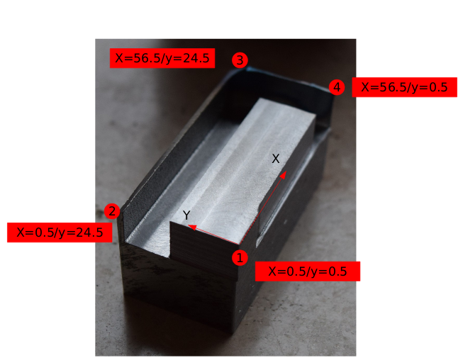
The raw material dimensions were 57mm x 25mm and i wanted to mill it to 56mm x 24mm.
The path from point 2 to 3 to 4 went wrong, but i do not understand why. In the tool table i added a 10mm tool.
Tanks for any hint.
Gcode:
G21 G17 G64 G90
F56
G0 Z5
G0 X-2 Y-2
G41 T10
Z-10
G1 X0.5 Y0.5
G1 X0.5 Y24.5
G1 X56.5 Y24.5
G1 X56.5 Y0.5
G1 X0.5 Y0.5
Please Log in or Create an account to join the conversation.
- curtisa
- Offline
- Premium Member
-

- Posts: 88
- Thank you received: 15
...
G41 T10
...
Cutter compensation uses the currently loaded tool to determine the correct offset from the intended path. By loading the tool after the compensation has been turned on the compensation may not 'know' what the new tool is and assumes it is whatever diameter was used up to the point it was turned on (in your case no tool was defined beforehand, so tool diameter would be zero).
Try calling tool T10 before calling G41 and see if that corrects the issue. Alternatively it looks like you can use G41 D10 as well. The D variable forces the compensation to use tool number 10 for every subsequent compensated move. More info here;
linuxcnc.org/docs/2.6/html/gcode/gcode.html#sec:G41-G42
Please Log in or Create an account to join the conversation.
- andypugh
-

- Offline
- Moderator
-

- Posts: 19782
- Thank you received: 4604
It seems to me that you wanted the cutter to the left of the chosen path?
Please Log in or Create an account to join the conversation.
- curtisa
- Offline
- Premium Member
-

- Posts: 88
- Thank you received: 15
To start cutter compensation to the left of the part profile, use G41. G41 starts cutter compensation to the left of the programmed line as viewed from the positive end of the axis perpendicular to the plane.
Based on the OPs picture it looks like his code started at point 1 and went clockwise around the part, G41 should have placed the cutter to the left as it went around the perimeter.
Edit: not so sure any more. The diagrams on this page make me think G42 might have been required rather than G41.
Please Log in or Create an account to join the conversation.
- Hakan
- Offline
- Platinum Member
-

- Posts: 1147
- Thank you received: 409
Please Log in or Create an account to join the conversation.
- jbraun
- Offline
- Senior Member
-

- Posts: 65
- Thank you received: 15
Axis shows the loaded tool at the bottom of the screen, I am not sure how the other interfaces display that information.
Please Log in or Create an account to join the conversation.
- MaHa
- Offline
- Platinum Member
-

- Posts: 503
- Thank you received: 210
Since cutter compensation in linuxcnc is kind of ¿?¿ ,it`s good advice to read this part of the manual.
Please Log in or Create an account to join the conversation.
- mane
- Offline
- Senior Member
-

- Posts: 46
- Thank you received: 1
Merry Christmas.
Mane
Please Log in or Create an account to join the conversation.
- jbraun
- Offline
- Senior Member
-

- Posts: 65
- Thank you received: 15
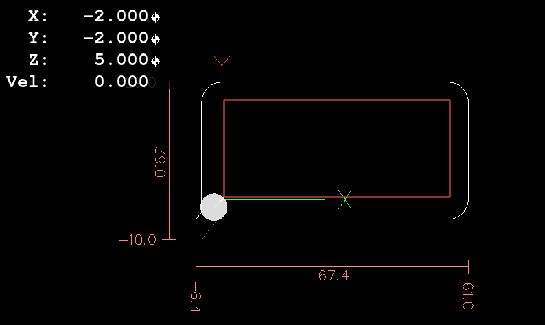
The red is your file with no tool loaded and no D in the G41 line. You need one or the other for linuxcnc to read the tool table.
The white is a compensated path with a lead-in, notice how it rolls around corners.
It's not hard programming if you follow the rules.
Merry Christmas to you as well.
Please Log in or Create an account to join the conversation.
- mane
- Offline
- Senior Member
-

- Posts: 46
- Thank you received: 1
To have no problem with tool cutter entry i added line 4 to be far away from the corner. But this does not help.
The error comes right after loading the program, in the status line bottom i have no tool loaded. And G54 DRO view does not change the values when i jog around the axis by keyboard.
1. G21 G17 G40 G49 G61 G90 G54
2. F56
3. G0 Z5
4. G0 X-20 Y-20

5. G41 D10
6. G1 Z1
7. G1 X0.5 Y0.5
8. G1 X0.5 Y24.5
9. G1 X56.5 Y24.5
10. G1 X56.5 Y0.5
11. G1 X0.5 Y0.5
12. M30Please Log in or Create an account to join the conversation.


