G64 P and Q - Strange behaviour
- pseudo
- Offline
- Junior Member
-

Less
More
- Posts: 23
- Thank you received: 7
14 Jan 2023 05:44 #261896
by pseudo
G64 P and Q - Strange behaviour was created by pseudo
Hey guys, I've encountered some odd behaviour with the naive cam detection/path blending and I'm curious as to whether this is expected behaviour and my understanding is wrong, or this indicates something else.
Context:
and observation 2: shouldn't setting a low value for naive cam detection not impact the path blending's behaviour for smoothing corners?
Final, slightly out there thought: could velocity feedforward or other similar cia402/ethercat elements impact this? System is currently running ethercat drives in cia402 position mode, without any PID on lincnc's end, could that be the cause?
Thanks in advance for people's insight
Context:
- Path is long, smooth curves (consisting of many small straight segments) with a horizontal lead out and a 2mm stepdown (see 'baseline' image below for an overview)
- Images are taken from the backplot, viewed along the Y axis (in images Z+ is up and X+ is right)
- Baseline setting of G64 P0.5 Q0.5 (machine units mm)
- System is an ethercat servo system, with accelerations set in linuxcnc far below what the drives and mechanics are able to do (ie the drives can comfortably keep up with LCNC's instructions)
- X axis is much faster top speed but slower accel than the other two axis.
- In the images the long gentle curves are ~1.8m and are run at 10m/min (machine cuts foam) and the total Z travel for the curve is only 50mm. The Z axis can comfortably keep up with X in these cuts
- There is no Y component to the motion in these shots.
- Rerunning any version results in identical results (ie hit start again and the traveled path on backplot lines up perfectly no matter the zoom level) suggesting it's not following error or similar, ie the trajectory planner is more likely the cause than drives/machine issues
- Not touching path:
- With G64 P0.5 Q0.5 set the traveled path on the backplot never touches the gcode path... for the entire 1800mm curve length. See images 'Baseline' and 'Baseline 2'.
- The curve starts low, Z=20, peaks at z=70, then drops back to approximately the same height. Even at the very long, near-horizonal section (ie where Z motion is near zero), the traveled path does not touch the gcode path, instead oscillating nearer and further away.
- Setting Q to low values seems to impact path blending:
- See the remaining images (q0.1, q0.01, q0.001)
- The P value for all images was 0.5
- Very low Q values seem to change how path blending is done, ie LCNC stops cutting corners and acts as though the P value has been reduced to the same value as Q. Image Q0.001 shows this the clearest, where it looks like exact path mode rather than blending, despite the path blending variable still being 0.5
- At Q=0.01 there's the tiniest corner cut (ie significantly smaller than P0.5 would theoretically produce) and at Q0.1 it looks more normal but the path on the long curve struggles to touch the intended line
and observation 2: shouldn't setting a low value for naive cam detection not impact the path blending's behaviour for smoothing corners?
Final, slightly out there thought: could velocity feedforward or other similar cia402/ethercat elements impact this? System is currently running ethercat drives in cia402 position mode, without any PID on lincnc's end, could that be the cause?
Thanks in advance for people's insight
Please Log in or Create an account to join the conversation.
- Lcvette
-

- Offline
- Platinum Member
-

Less
More
- Posts: 1630
- Thank you received: 760
14 Jan 2023 08:18 #261907
by Lcvette
Replied by Lcvette on topic G64 P and Q - Strange behaviour
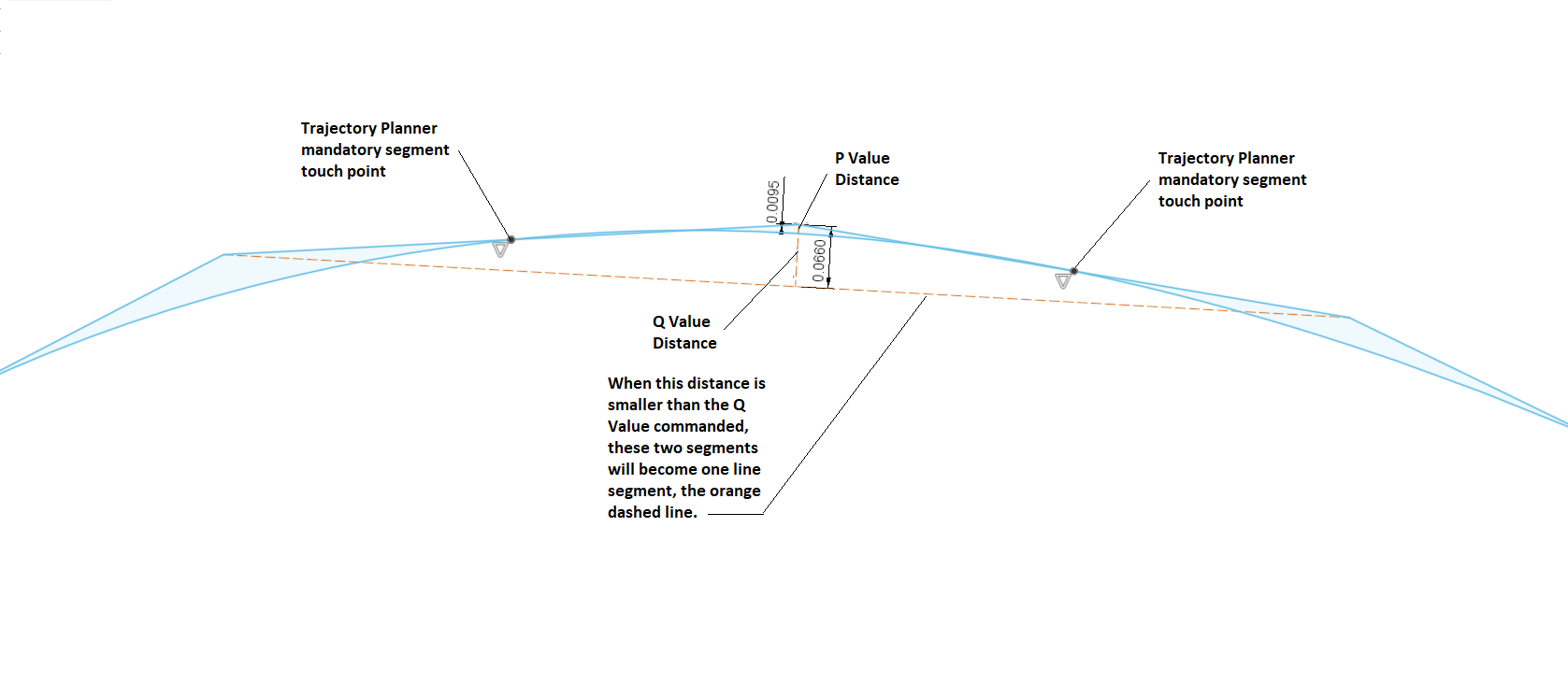
from my current research, the Q value determines when to collapse connecting line segments based on how far their joint is from being collinear with their outer endpoints. this reduces the number of small segments in the trajectory planner. the P value determines how far away from the joint of 2 line segments the path can deviate. this is the rounding of corners you would experience. so if Q value shrinks and more line segments are present, this will force the path to more closely follow the existing Gcode lines by way of creating more points for which the P value is applied to. we also know that the trajectory planner must touch each line segment at least once, so even if the P value is set very high, the TP cannot deviate by very much give such a short distance between two consecutive contacts on each small segment.
as the Q value grows and more of small segments are merged into longer segments, the distance and amount of freedom between the two segment touch points and their joint increases allowing for the ability to achieve larger P value settings.
here is a rudimentary graphical representation as I understand it. if I have this wrong please someone correct me!
Attachments:
The following user(s) said Thank You: pseudo
Please Log in or Create an account to join the conversation.
- andypugh
-

- Offline
- Moderator
-

Less
More
- Posts: 19871
- Thank you received: 4640
14 Jan 2023 10:18 #261913
by andypugh
Replied by andypugh on topic G64 P and Q - Strange behaviour
The path you see in the preview has no dependance on anything external to the software and settings.
The system tries to do the best it can within your G64 limits _and_ the acceleration and velocity limits in the INI.
You mention that the iNI acceleration and velocity are conservative relative to what the machine can really do. I think that you will see far better path following if you increase the INI values to be less conservative (especially the acceleration)
The following user(s) said Thank You: pseudo
Please Log in or Create an account to join the conversation.
- pseudo
- Offline
- Junior Member
-
Less
More
- Posts: 23
- Thank you received: 7
16 Jan 2023 04:30 #262091
by pseudo
Replied by pseudo on topic G64 P and Q - Strange behaviour
Hey guys, thanks for the swift and detailed responses; Lcvette your explanation and drawing helped clear some things up for me too.
The issue I'm having is what I'm seeing doesn't match those described behaviours (or I've misunderstood or missed something, in which case thanks in advance for your patience) in two key ways:
andypugh: Y and Z have very little work to do to keep up with X (long shallow curves) but they've got plenty of accel left on the table so I'll crank their accel right up and see what I get.
Cheers for your time guys.
Additional question/thought: is there a way to export/log the traveled path (ie the red line in backplot)?
The issue I'm having is what I'm seeing doesn't match those described behaviours (or I've misunderstood or missed something, in which case thanks in advance for your patience) in two key ways:
- "..the trajectory planner must touch each line segment at least once" - I'm seeing over a meter of travel, with around a thousand segments, where the path doesn't touch at all (see 'not touching points' image for hasty mspaint diagram) unless Q is set extremely low (0.5 = no touching/intersection, 0.01 does touch).
- Could this be due to some sort of averaging of the path? ie when niave cam detection acts across all segments in a long convex curve it averages the curve out towards flat?
- Low Q + lots of points = less freedom for P to act - This is where I'm more sure that the behaviour is odd: at the end of each curve is a 30mm horizontal lead out, 2mm step down, then 30mm lead in. When Q is set very low (ie to more accurately trace the curved paths) the lead ins and lead outs also get traced more accurately, as if the P value is ignored (see 'negated P' image).
- These motions are four points: (I just checked the gcode to be sure)
- end of curve/start of lead out,
- end of lead out +30mm in X
- stepdown -2mm in Z
- lead in/start of next curve -30mm in X
- These motions are four points: (I just checked the gcode to be sure)
andypugh: Y and Z have very little work to do to keep up with X (long shallow curves) but they've got plenty of accel left on the table so I'll crank their accel right up and see what I get.
Cheers for your time guys.
Additional question/thought: is there a way to export/log the traveled path (ie the red line in backplot)?
Please Log in or Create an account to join the conversation.
- Todd Zuercher
-

- Offline
- Platinum Member
-
Less
More
- Posts: 4753
- Thank you received: 1458
16 Jan 2023 15:42 - 16 Jan 2023 15:56 #262134
by Todd Zuercher
Replied by Todd Zuercher on topic G64 P and Q - Strange behaviour
I believe that if you set Q=0 it will turn off the Naive CAM Detection and the path should then touch a point on every line segment, if that is what you are wanting.
PS If Q is very low or zero, then yes, there will not be room for P to use it's full blending tolerance if line segments are short enough to not allow the full tolerance and still touch the segment. Pretty much if any segment is less than twice P it will limit the amount of blending regardless of the length of adjacent segments. Having a large P and very small Q will likely result in mixed tolerance results where parts of the code with short segments will have a close tolerance but any corners with adjacent long segments will be significantly rounded.
PS If Q is very low or zero, then yes, there will not be room for P to use it's full blending tolerance if line segments are short enough to not allow the full tolerance and still touch the segment. Pretty much if any segment is less than twice P it will limit the amount of blending regardless of the length of adjacent segments. Having a large P and very small Q will likely result in mixed tolerance results where parts of the code with short segments will have a close tolerance but any corners with adjacent long segments will be significantly rounded.
Last edit: 16 Jan 2023 15:56 by Todd Zuercher. Reason: added PS
The following user(s) said Thank You: pseudo
Please Log in or Create an account to join the conversation.
- pseudo
- Offline
- Junior Member
-
Less
More
- Posts: 23
- Thank you received: 7
22 Jan 2023 23:55 #262689
by pseudo
Replied by pseudo on topic G64 P and Q - Strange behaviour
That's the weird thing, large P and low Q should round corners on segments where points are sparse but it's not, see the 'negated P' image in my previous post for a diagram of what I'm seeing. Basically with P0.5 and Q0.5 the lead ins and lead outs (large rectangular moves) are being rounded as expected, but with P0.5 and q0.01 they're not, instead it's sticking within Q tolerance of the points.
Unless I've missed something (which is entirely possible of course) everyone (including me) agrees on what P and Q should do in this situation but my observations don't match that, any ideas on what to check next?
Unless I've missed something (which is entirely possible of course) everyone (including me) agrees on what P and Q should do in this situation but my observations don't match that, any ideas on what to check next?
Please Log in or Create an account to join the conversation.
- Todd Zuercher
-
- Offline
- Platinum Member
-
Less
More
- Posts: 4753
- Thank you received: 1458
23 Jan 2023 13:21 #262742
by Todd Zuercher
Replied by Todd Zuercher on topic G64 P and Q - Strange behaviour
Large P and small Q, WILL round the corners. In fact it will have it's maximum rounding effect when points are far apart. If line segment length is less than Q, the requirement of touching a point on the segments less than Q in length will be dropped and only held to staying withing P for those short segments. That is why on curves approximated by short segments the tool path doesn't precisely follow the programed path there.
Please Log in or Create an account to join the conversation.
- pseudo
- Offline
- Junior Member
-
Less
More
- Posts: 23
- Thank you received: 7
06 Feb 2023 00:18 #263780
by pseudo
Replied by pseudo on topic G64 P and Q - Strange behaviour
There must be something screwy with my setup then as large P and small Q is emphatically not rounding long sparse segments... however you're still a lifesaver as setting Q to 0 (ie off) mixed with a reasonable P value and getting the CAM dev to include a point spacing variable to play with (ie I can now tell the weird niche CAM to aim for n mm between points) has solved the issue. Cheers Todd
Please Log in or Create an account to join the conversation.
Time to create page: 0.257 seconds