Hal Show not agreeing with parallel port signals
- jensor
-
 Topic Author
- Offline
- Premium Member
-

Less
More
- Posts: 84
- Thank you received: 4
17 Aug 2019 19:49 - 17 Aug 2019 19:53 #142407
by jensor
Hal Show not agreeing with parallel port signals was created by jensor
In my .hal file:
#create a signal and connect to parport pin for estop activated for Estop-on (red) ind
net estopactivated halui.estop.is-activated parport.1.pin-03-out
# now create a signal for estop not activated for Estop-off ind (grn) & motor control
net estopactivated => parport.1.pin-04-out
setp parport.1.pin-04-out-invert true
Therefor I would believe that pins 3 and 4 should be opposite of each other.
However,
Upon start of Axis and into Hal Configuration/Watch I see parport.1.pin-03 "on" while actual pin is 0 volts - means Estop activated
at same time I see parport.1.pin-04 "on" while actual pin is 4.7 volts - means Estop not activated.
How can this be? Those signals on pins 3 and 4 should be opposite of each other, shouldn't they?
Attachments:
Last edit: 17 Aug 2019 19:53 by jensor. Reason: Add text
Please Log in or Create an account to join the conversation.
- PCW
-

- Away
- Moderator
-

Less
More
- Posts: 17985
- Thank you received: 5277
17 Aug 2019 20:09 #142408
by PCW
Replied by PCW on topic Hal Show not agreeing with parallel port signals
I think that's correct, the output state of the hal parallel port pin is
whatever you set it to, but the actual physical output pin polarity
can be true or inverted depending on the state of the out-invert parameter.
whatever you set it to, but the actual physical output pin polarity
can be true or inverted depending on the state of the out-invert parameter.
Please Log in or Create an account to join the conversation.
- jensor
-
Topic Author
- Offline
- Premium Member
-
Less
More
- Posts: 84
- Thank you received: 4
18 Aug 2019 12:47 - 18 Aug 2019 12:51 #142434
by jensor
Replied by jensor on topic Hal Show not agreeing with parallel port signals
But shouldn't pin 3 and 4 always be opposite of each other with the given Hal statements?
Hal Show indicates true on both pins simultaneously. How is this possible?
My goal is to have a Red indicator when Estop is activated and a Green indicator when Estop is inactivated. They can't both be lit simultaneously.
Hal Show indicates true on both pins simultaneously. How is this possible?
My goal is to have a Red indicator when Estop is activated and a Green indicator when Estop is inactivated. They can't both be lit simultaneously.
Last edit: 18 Aug 2019 12:51 by jensor. Reason: Add text.
Please Log in or Create an account to join the conversation.
- tommylight
-

- Away
- Moderator
-
Less
More
- Posts: 21734
- Thank you received: 7425
18 Aug 2019 12:50 - 18 Aug 2019 12:51 #142435
by tommylight
Replied by tommylight on topic Hal Show not agreeing with parallel port signals
You wrote above:
Pin 3 for estop on
Pin 4 for estop off
Pin 4 inverted true.
That makes the both act the same.
Remove invert.
Pin 3 for estop on
Pin 4 for estop off
Pin 4 inverted true.
That makes the both act the same.
Remove invert.
Last edit: 18 Aug 2019 12:51 by tommylight. Reason: typo
Please Log in or Create an account to join the conversation.
- jensor
-
Topic Author
- Offline
- Premium Member
-
Less
More
- Posts: 84
- Thank you received: 4
18 Aug 2019 12:53 #142436
by jensor
Replied by jensor on topic Hal Show not agreeing with parallel port signals
Thanks. I'll give that a try after I get back from church.
Please Log in or Create an account to join the conversation.
- PCW
-
- Away
- Moderator
-
Less
More
- Posts: 17985
- Thank you received: 5277
18 Aug 2019 14:30 - 18 Aug 2019 14:34 #142441
by PCW
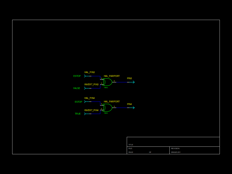
Yes its possible because the inversion only affects the output state, not the hal pin, Something like this:
Replied by PCW on topic Hal Show not agreeing with parallel port signals
But shouldn't pin 3 and 4 always be opposite of each other with the given Hal statements?
Hal Show indicates true on both pins simultaneously. How is this possible?
My goal is to have a Red indicator when Estop is activated and a Green indicator when Estop is inactivated. They can't both be lit simultaneously.
Yes its possible because the inversion only affects the output state, not the hal pin, Something like this:
Attachments:
Last edit: 18 Aug 2019 14:34 by PCW.
The following user(s) said Thank You: tommylight
Please Log in or Create an account to join the conversation.
- jensor
-
Topic Author
- Offline
- Premium Member
-
Less
More
- Posts: 84
- Thank you received: 4
19 Aug 2019 12:07 - 19 Aug 2019 12:27 #142490
by jensor
Replied by jensor on topic Hal Show not agreeing with parallel port signals
I don't understand the diagram. The 7416 shown is listed as a hex inverter gate. You are using a logic symbol for a nor gate. Very confusing to me. Could you explain further and or add a truth table?
Also is a Hal parallel port pin different from the actual parallel port pin? That would kind of make sense to me because as I see it, Hal is telling the parallel port card what to do but does not really know what the parallel card is actually doing. Somewhat like a driver telling a stepper motor to do a step but the driver doesn't know if the motor obeyed the command.
Also is a Hal parallel port pin different from the actual parallel port pin? That would kind of make sense to me because as I see it, Hal is telling the parallel port card what to do but does not really know what the parallel card is actually doing. Somewhat like a driver telling a stepper motor to do a step but the driver doesn't know if the motor obeyed the command.
Last edit: 19 Aug 2019 12:27 by jensor. Reason: Add text.
Please Log in or Create an account to join the conversation.
- PCW
-
- Away
- Moderator
-
Less
More
- Posts: 17985
- Thank you received: 5277
19 Aug 2019 13:54 - 19 Aug 2019 13:58 #142493
by PCW
Replied by PCW on topic Hal Show not agreeing with parallel port signals
The gate/symbol is an exclusive or gate (its a 7486 but the conversion to png lost some details)
Its truth table is as follows:
Note that when IN1 is 0, the output follows IN2 but when IN1 is 1, the output is the logical inversion of IN2
So the driver hal pin reflects what it has been set it to in hal but at the actual physical pin
the output can be a true or inverted copy of the hal pin based on the invert option.
Some other hardware allows what you are suggesting but is does it by having two hal pins per
physical pin, an input and and an output pin, where the output pin reflects the hal pin state and
the input pin reflects the actual read back state of the physical pin.
Its truth table is as follows:
in1 in2  out
0   0    0
0   1    1
1   0    1
1   1    0
Note that when IN1 is 0, the output follows IN2 but when IN1 is 1, the output is the logical inversion of IN2
So the driver hal pin reflects what it has been set it to in hal but at the actual physical pin
the output can be a true or inverted copy of the hal pin based on the invert option.
Some other hardware allows what you are suggesting but is does it by having two hal pins per
physical pin, an input and and an output pin, where the output pin reflects the hal pin state and
the input pin reflects the actual read back state of the physical pin.
Last edit: 19 Aug 2019 13:58 by PCW.
Please Log in or Create an account to join the conversation.
Time to create page: 0.611 seconds