how to implement a dual spindle system (Z and A)
- kevin19
- Offline
- Junior Member
-

Less
More
- Posts: 35
- Thank you received: 0
11 Sep 2020 14:05 - 11 Sep 2020 14:06 #181763
by kevin19
how to implement a dual spindle system (Z and A) was created by kevin19
Hello, my machine will look like the one in the picture below.
As we can see the first camera (the one with low magnification) is attached to the Z axis plate and the second high magnification camera is mounted on the Standa precision rail (shown in faded blue in my image) which can be called A. The position of the first camera depends only on the Z axis whereas the position of the second camera will depend on both Z axis and A axis and they both are parallel to each other.
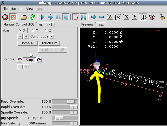
Currently when I open the emc axis_mm I just have a single cone as you can see in the image below but in my case I should have 2 cones(dual spindle).
And at the end if everything works as planned, when I change Z both cameras should be moving and when I change A only the second camera should be moving.
Can someone help me on this?
Attachments:
Last edit: 11 Sep 2020 14:06 by kevin19.
Please Log in or Create an account to join the conversation.
- Todd Zuercher
-

- Online
- Platinum Member
-

Less
More
- Posts: 4696
- Thank you received: 1439
11 Sep 2020 16:53 #181773
by Todd Zuercher
Replied by Todd Zuercher on topic how to implement a dual spindle system (Z and A)
It sounds more like your second camera would be mounted to a 2nd parallel Z axis. This is customarily given the axis letter W. The axis letters A,B, and C generally refer to rotary axis about the X,Y, and Z axis respectively.
I have several CNC routers running Linuxcnc, set up with two spindles mounted to separate parallel Zs one called Z and the other W.
However I do not know of a way to make the display show two tools. (I do not think it is possible without rewriting the display program.)
I have several CNC routers running Linuxcnc, set up with two spindles mounted to separate parallel Zs one called Z and the other W.
However I do not know of a way to make the display show two tools. (I do not think it is possible without rewriting the display program.)
Please Log in or Create an account to join the conversation.
- kevin19
- Offline
- Junior Member
-

Less
More
- Posts: 35
- Thank you received: 0
11 Sep 2020 17:39 - 11 Sep 2020 17:40 #181776
by kevin19
Replied by kevin19 on topic how to implement a dual spindle system (Z and A)
Yeah the second camera would be indeed mounted to a 2nd parallel Z axis as you said. It would be really great if you could share with me how you did to set up those dual spindles on your system (Z and W in your case).
That would really be helpful for me!
That would really be helpful for me!
Last edit: 11 Sep 2020 17:40 by kevin19.
Please Log in or Create an account to join the conversation.
- kevin19
- Offline
- Junior Member
-

Less
More
- Posts: 35
- Thank you received: 0
13 Sep 2020 23:38 - 13 Sep 2020 23:44 #182043
by kevin19
Replied by kevin19 on topic how to implement a dual spindle system (Z and A)
Last edit: 13 Sep 2020 23:44 by kevin19.
Please Log in or Create an account to join the conversation.
- Aciera
-

- Offline
- Administrator
-

Less
More
- Posts: 4653
- Thank you received: 2078
14 Sep 2020 06:04 #182055
by Aciera
Replied by Aciera on topic how to implement a dual spindle system (Z and A)
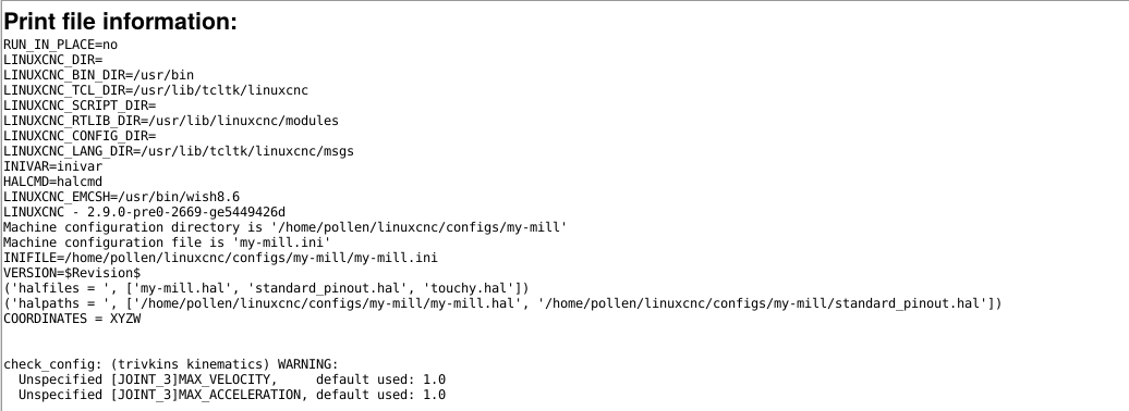
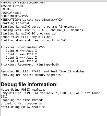
The values for joint_3 in the INI are commented out.
Warning: Spoiler!
[JOINT_3]
#TYPE = ANGULAR
#HOME = 0.0
#MAX_VELOCITY = 90.0
#MAX_ACCELERATION = 360.0
#STEPGEN_MAXACCEL = 396.0
#BACKLASH = 0.000
#SCALE = 40
#OUTPUT_SCALE = 1.000
#MIN_LIMIT = -36000.0
#MAX_LIMIT = 36000.0
#FERROR = 5.0
#MIN_FERROR = 1.0
#HOME_OFFSET = 0.0
#HOME_SEARCH_VEL = 0.0
#HOME_LATCH_VEL = 0.0
#HOME_USE_INDEX = NO
#HOME_IGNORE_LIMITS = NO
The following user(s) said Thank You: kevin19
Please Log in or Create an account to join the conversation.
- Todd Zuercher
-

- Online
- Platinum Member
-

Less
More
- Posts: 4696
- Thank you received: 1439
15 Sep 2020 17:48 #182250
by Todd Zuercher
Replied by Todd Zuercher on topic how to implement a dual spindle system (Z and A)
Here is a copy of my config files.
forum.linuxcnc.org/media/kunena/attachments/3190/Digital_1.zip
forum.linuxcnc.org/media/kunena/attachments/3190/Digital_1.zip
Please Log in or Create an account to join the conversation.
Time to create page: 0.137 seconds


