SPI bus generic driver and ST L6480
- mariusl
-

- Offline
- Platinum Member
-

10 Mar 2015 00:00 #56583
by mariusl
Regards
Marius
www.bluearccnc.com
Replied by mariusl on topic SPI bus generic driver and ST L6480
Thanks I will check it out in the next couple of days.
Regards
Marius
www.bluearccnc.com
Please Log in or Create an account to join the conversation.
- yeltrow
- Offline
- Senior Member
-

Less
More
- Posts: 65
- Thank you received: 3
10 Mar 2015 05:11 - 14 Mar 2015 20:24 #56605
by yeltrow
Replied by yeltrow on topic SPI bus generic driver and ST L6480
I noticed that spiclient.comp had the hold pin set to 0 (meaning wait until hold = 1 to run). That would keep the spiclient.comp test component from transitioning to the run state to make pretty scope plots ") Right now stm.comp is the component I am testing spi commands to my EVAL6480H with. I am getting some core dumps due to warn_slow_???? Not sure what I am doing wrong there, but if you try stm.comp out, prepare for the worst...
Right now stm.comp is the component I am testing spi commands to my EVAL6480H with. I am getting some core dumps due to warn_slow_???? Not sure what I am doing wrong there, but if you try stm.comp out, prepare for the worst...
Of these files max7219ds.comp should work fine with maxtest.hal. You can use it to make one of the 8 digit 7 segment displays count up to 99999999 on your parallel port.
spiclient.comp should work fine with spitest.hal just to show how stuff can work.
stm.comp causes my machine to crash. Still working through that.
-- UPDATE - REMOVED files -- see later post in this thread for better working versions --
Right now stm.comp is the component I am testing spi commands to my EVAL6480H with. I am getting some core dumps due to warn_slow_???? Not sure what I am doing wrong there, but if you try stm.comp out, prepare for the worst...Of these files max7219ds.comp should work fine with maxtest.hal. You can use it to make one of the 8 digit 7 segment displays count up to 99999999 on your parallel port.
spiclient.comp should work fine with spitest.hal just to show how stuff can work.
stm.comp causes my machine to crash. Still working through that.
-- UPDATE - REMOVED files -- see later post in this thread for better working versions --
Last edit: 14 Mar 2015 20:24 by yeltrow.
Please Log in or Create an account to join the conversation.
- yeltrow
- Offline
- Senior Member
-
Less
More
- Posts: 65
- Thank you received: 3
11 Mar 2015 04:57 - 12 Mar 2015 18:43 #56645
by yeltrow
Replied by yeltrow on topic SPI bus generic driver and ST L6480
The stack pointer in the stm.comp component (just another example component that I am gradually turning into a real driver for a the L6480 chip) had a problem with the callstack blowing up after state 102. Intead of exiting to state 103, it moves on to 104. I figured out that I had skipped a break statement. Stacking two transmits on top of each other caused the stack to blow up.
I have found a REAL problem with the SPI driver itself -- I was bitshifting inputs the wrong direction. The datasheet for the L6480 also shows a return to hi setup for the clock, but it doesn't seem to actually behave that way. When I drop the clock line after the chipselect, it does not prepare the MSB for the response, instead, it waits until after the clock cycles hi and then back to low before presenting the first bit (MSB). This causes all my responses to be shifted over one place. Worse, it seems my last bit (the LSB) doesn't show up until the next byte is cycled out. Data going out the chip seems to be getting there fine, so that is probably why the max7219ds.comp driver works.
I have found a REAL problem with the SPI driver itself -- I was bitshifting inputs the wrong direction. The datasheet for the L6480 also shows a return to hi setup for the clock, but it doesn't seem to actually behave that way. When I drop the clock line after the chipselect, it does not prepare the MSB for the response, instead, it waits until after the clock cycles hi and then back to low before presenting the first bit (MSB). This causes all my responses to be shifted over one place. Worse, it seems my last bit (the LSB) doesn't show up until the next byte is cycled out. Data going out the chip seems to be getting there fine, so that is probably why the max7219ds.comp driver works.
Last edit: 12 Mar 2015 18:43 by yeltrow. Reason: New information
Please Log in or Create an account to join the conversation.
- yeltrow
- Offline
- Senior Member
-
Less
More
- Posts: 65
- Thank you received: 3
14 Mar 2015 20:27 #56809
by yeltrow
Replied by yeltrow on topic SPI bus generic driver and ST L6480
Working -- Looks like the root of my problem was actually that the parport isn't getting
it's signals out and settled long enough before I read the inputs. I added a slowdown
input pin to the spibus to get it skip execution for how many ever cycles are specified
in slowdown. This made it act right with the spibus driver as originally written from the
timing diagrams. I can only get it to pump out about 2.5 bytes per millisecond instead of
5, which stinks. I haven't dug into why it won't go faster yet. This is with a 10us base
period. Those $89 Mesa FPGA cards are looking better all the time
Notes about running this snapshot:
stm.comp
1) parport.0.pin-05-out = 1 is needed to set the reset pin on the board in the right state.
2) stm.0.hold = 1 is needed to enable the driver. Counterintuitive name, FIXME.
Next step would be to get it monitor its position and feed it back to a variable as well
as accept velocity commands so it really could provide a joint driver to linuxcnc.
Motor runs! State machine cleaned up to make key blocks into "STATE MACHINE FUNCTIONS."
Program flow much easier to follow now. Still need to make it into something that looks like
a useful hal motor driver.
Please Log in or Create an account to join the conversation.
- yeltrow
- Offline
- Senior Member
-
Less
More
- Posts: 65
- Thank you received: 3
15 Mar 2015 19:31 #56841
by yeltrow
Replied by yeltrow on topic SPI bus generic driver and ST L6480
This snapspot has a float pin targetVelocity as input that is in inches i
per second as the command speed for the stepper. When the stm.comp driver
comes up, it reads the cxxxxxx config variables and writes them to the drive.
Then it immediately goes into a mode waiting for velocity commands.
I did learn last night the actual order of the components loaded into the base
thread was read parport, write parport, run components. This was bad because
the commands wouldn't be acted on until after a read cycle. This is why I
needed the "slowdown" input to the spibus.comp driver. It is no longer needed
and the spibus driver can clock out data at 1/2 bit per base-thread cycle.
In my case, that is 5.5bytes/millisecond.
Please Log in or Create an account to join the conversation.
- yeltrow
- Offline
- Senior Member
-
Less
More
- Posts: 65
- Thank you received: 3
09 Apr 2015 09:21 - 09 Apr 2015 09:49 #57641
by yeltrow
Replied by yeltrow on topic SPI bus generic driver and ST L6480
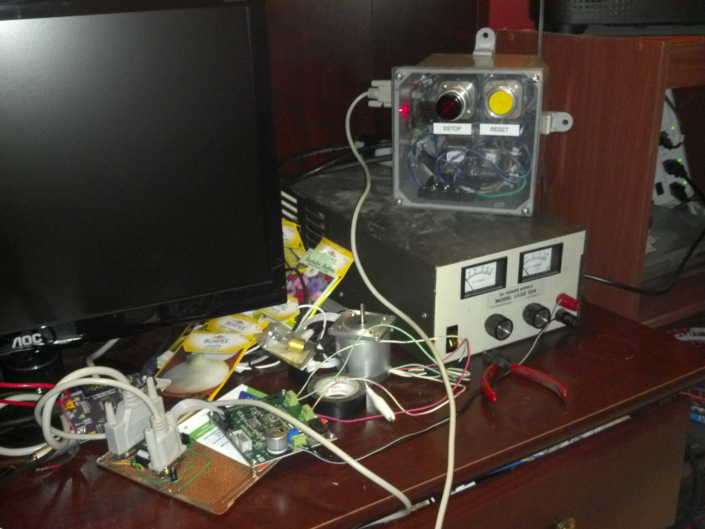
2015-04-08-21_59 IT WORKS!!!!
BTW -- If you decide to use one of the EVAL6480H boards, be sure to put a resistor onto the reset pin (see attached schematic). I forgot about the little zener clamp diode and send over and amp into the clamp diode. Luckily, it failed shorted and protected the chip when I unplugged the ribbon cable. If it had burned in half, the full drive supply voltage could have been put across the reset pin and cooked it. I had a 3.3V zener of the same surface mount size and repaired the drive tonight. I have also modified the jumper settings on the board so I can force 5V into VDD through the spi ribbon cable. The drive works with the jumper settings either way, but could be producing very weak signals back to the PC which would be more succeptable to noise. Below is the readme for this file set:
Hurray!!! It works! I have a single axis working seamlessly over the spibus with
an external estop. The driver can now run a single axis and react appropriately
when the estop button is pressed. I have my new breakout board prototyped up that
pipes the e-stop signal to the reset line so the chip is held in reset as soon
as the estop circuit activates. The noEstop input pin on the stm.comp component
will drop back to initialize the drive when it sees a 0 indicating the estop circuit
has been tripped. It will then sit in a loop continuously querying the drive
until it gets sensible status information from the drive. It then loops checking
all of the configuration parameters to make sure they are correct and then proceeds
to a "ready" state when successful. I have added a totally bogus charge pump output
on pin 17 to enable my estop box.
Next Steps:
1) The charge pump output needs tied into the estop buttons on Axis.
2) Tie in some sort of monitoring of the feedback from the motor to make sure
it is valid. Currently I am integrating the velocity commands and computing
when I should have seen a step change from the controller's internal position
counter. Under high accelleration, this method isn't perfect. It isn't set
as any kind of a fault yet. It should be so we know if the drive is being stupid.
3) Testing with multiple axes.
4) Testing for interference with the big motors and power supply on the mill.
5) Relocating the components to their new home in the control panel on the mill.
6) Integration of mill limit switches
7) Integration of oiler, coolant, spindle control, jog wheels, maybe encoders, and
other goodies.
Last edit: 09 Apr 2015 09:49 by yeltrow.
Please Log in or Create an account to join the conversation.
- mariusl
-
- Offline
- Platinum Member
-
09 Apr 2015 14:25 #57643
by mariusl
Does this hold true for all three channels? How many bytes do you get to read per cycle?
This looks really great so far. I have done a set of I/O cards that work on SPI or I2C. They can daisy chain to multiply. I will have a look at adapting them to fit your scheme at some stage. I only have a very basic driver to test with for now. I always intended for the I/O to go on a second parport and leave the first parport for the motors.
Regards
Marius
www.bluearccnc.com
Replied by mariusl on topic SPI bus generic driver and ST L6480
In my case, that is 5.5bytes/millisecond.
Does this hold true for all three channels? How many bytes do you get to read per cycle?
This looks really great so far. I have done a set of I/O cards that work on SPI or I2C. They can daisy chain to multiply. I will have a look at adapting them to fit your scheme at some stage. I only have a very basic driver to test with for now. I always intended for the I/O to go on a second parport and leave the first parport for the motors.
Regards
Marius
www.bluearccnc.com
Please Log in or Create an account to join the conversation.
- mariusl
-
- Offline
- Platinum Member
-
09 Apr 2015 15:53 #57644
by mariusl
Regards
Marius
www.bluearccnc.com
Replied by mariusl on topic SPI bus generic driver and ST L6480
Just one thing I cannot seem to get my head around with this driver. What mode or command are you using to drive the motor with. The reason I ask is I am not sure how the a synchronized move with three motors will be achieved.
Regards
Marius
www.bluearccnc.com
Please Log in or Create an account to join the conversation.
- yeltrow
- Offline
- Senior Member
-
Less
More
- Posts: 65
- Thank you received: 3
09 Apr 2015 19:25 #57647
by yeltrow
Replied by yeltrow on topic SPI bus generic driver and ST L6480
My base plan is to have a dedicated spibus for each axis (3 or 4 in total). If I can prove that my following errors are small enough with a 3ms servo loop, I can put all of the drives on one spibus. I have not proven that yet. To keep the axes together, I use a PID loop with a feed-forward velocity coefficient of 1 (FF1) so the motor is really getting a velocity command slightly tweaked by the position error to compensate for delays and clock skew. It is adorable that the little stepper thinks it is a servo I use the RUN(dir, speed) mode to run the motor at a velocity. I then use the PID to close the position reported by the L6480 against the command position. With pretty aggressive acceleration, I can still maintain a < 0.001 inch following error, so that isn't too bad. I dislike using the PID (which is all P in this setup, the I comes from position being the integral of velocity), but with the heavy FF component, it is just trimming the position a touch. I have also created a delayline component as an experiment to make the PID only trim against the position command that it has had time act against. I found that the position error from a command 4ms ago was always VERY small. I don't really care if my parts come out 4ms later than I commanded them to, so I am considering telling axis that the position is the command position + the pid error from 4ms ago. It reduces the closed loop bandwidth considerably, but it appears I may not need it. This may even suggest that 3ms updates would be fine. A real encoder could be used instead, and I am considering that, too. Every loop cycle i send GET_PARAM ABS_POS and RUN VELOCITY. It is nice that I get to receive the ABS_POS while I am clocking out the data for how fast to go. I have been simulating (with hardware in the loop) speeds of up to 60in/minute with 5TPI leadscrews. At 60 in/minute, the motion planner seems to like to make rounded corners anyway, so my loops may be the least of worries if I am running that fast. I predict most of the time I will be running in the <10in/minute speed range.
I use the RUN(dir, speed) mode to run the motor at a velocity. I then use the PID to close the position reported by the L6480 against the command position. With pretty aggressive acceleration, I can still maintain a < 0.001 inch following error, so that isn't too bad. I dislike using the PID (which is all P in this setup, the I comes from position being the integral of velocity), but with the heavy FF component, it is just trimming the position a touch. I have also created a delayline component as an experiment to make the PID only trim against the position command that it has had time act against. I found that the position error from a command 4ms ago was always VERY small. I don't really care if my parts come out 4ms later than I commanded them to, so I am considering telling axis that the position is the command position + the pid error from 4ms ago. It reduces the closed loop bandwidth considerably, but it appears I may not need it. This may even suggest that 3ms updates would be fine. A real encoder could be used instead, and I am considering that, too. Every loop cycle i send GET_PARAM ABS_POS and RUN VELOCITY. It is nice that I get to receive the ABS_POS while I am clocking out the data for how fast to go. I have been simulating (with hardware in the loop) speeds of up to 60in/minute with 5TPI leadscrews. At 60 in/minute, the motion planner seems to like to make rounded corners anyway, so my loops may be the least of worries if I am running that fast. I predict most of the time I will be running in the <10in/minute speed range. Please Log in or Create an account to join the conversation.
- mariusl
-
- Offline
- Platinum Member
-
09 Apr 2015 19:33 #57648
by mariusl
Regards
Marius
www.bluearccnc.com
Replied by mariusl on topic SPI bus generic driver and ST L6480
It is sounding like a good solution. I like what you are doing here man.
I am going to use a stm32 as base unit and then I might be able to run at 1ms loop time.
I am going to use a stm32 as base unit and then I might be able to run at 1ms loop time.
Regards
Marius
www.bluearccnc.com
Please Log in or Create an account to join the conversation.
Time to create page: 0.176 seconds