BLDC and fanuc redcap parameter problems?
- johns00056
- Offline
- Senior Member
-

- Posts: 58
- Thank you received: 2
CFG=qh
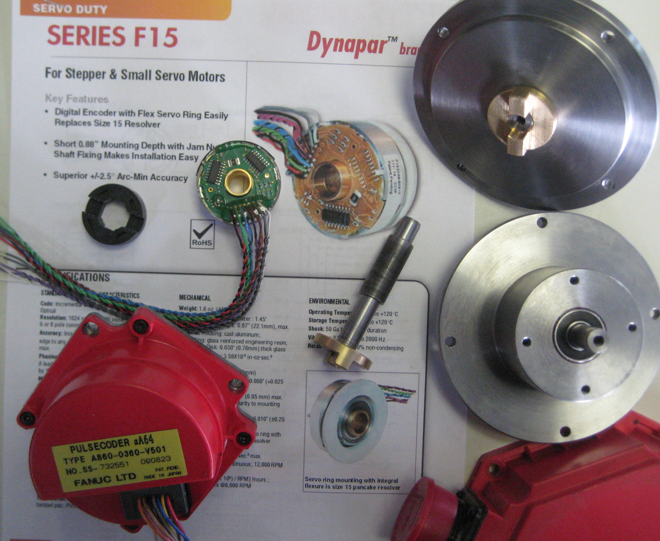
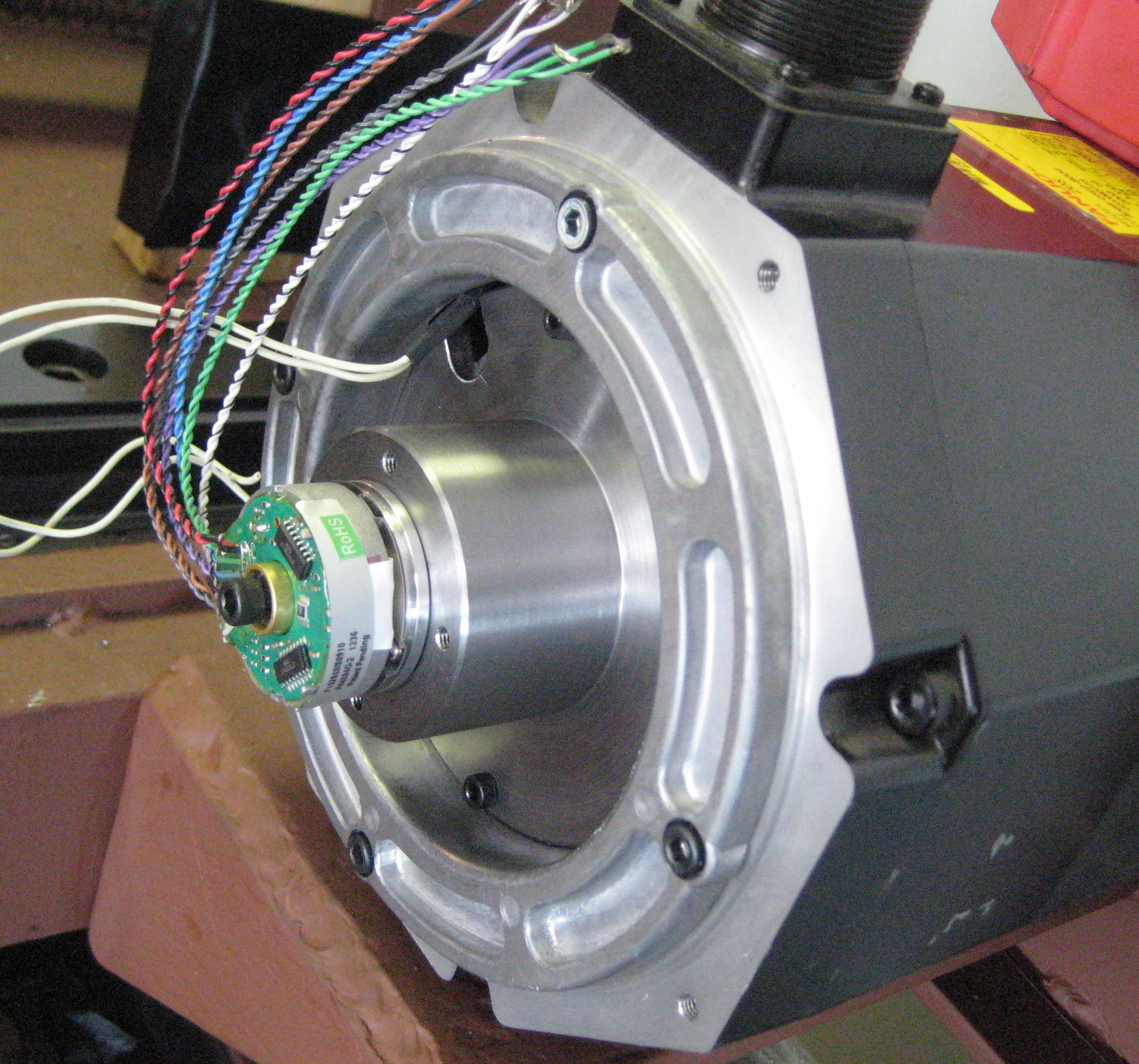
I replaced the Fanuc encoders with industry standard encoders with a commutation track.
I ended up with pattern 22 on three motors and pattern 25 on one . All four motors look the same so I am not sure why the "odd man out."
Please Log in or Create an account to join the conversation.
- andypugh
-

- Offline
- Moderator
-

- Posts: 19797
- Thank you received: 4606
I think that this is what you would expect. There are 6 phases to the pattern, so you can start in 6 places. And you can run through the pattern in two directions, to that will give you 12 possible valid combinations that all look identical to the drive.I did this test for all 48 BLDC patterns and about 12 of them gave a steady green led while rotating the motor shaft.
Next, I tried all 6 motor power lead combinations for each of the 12 BLDC patterns that gave a solid green led. None of the combinations gave a decent running motor. The best I got was quite rough.
This might just be the 16 into 6 problem. It might be worth trying the best of the rough-but-rotating setups without the T setting. (I have looked at my code, and can't quite decide what the effect of T is in your case)
Please Log in or Create an account to join the conversation.
- gmouer
- Offline
- Elite Member
-

- Posts: 212
- Thank you received: 9
I think that this is what you would expect. There are 6 phases to the pattern, so you can start in 6 places. And you can run through the pattern in two directions, to that will give you 12 possible valid combinations that all look identical to the drive.I did this test for all 48 BLDC patterns and about 12 of them gave a steady green led while rotating the motor shaft.
Next, I tried all 6 motor power lead combinations for each of the 12 BLDC patterns that gave a solid green led. None of the combinations gave a decent running motor. The best I got was quite rough.
This might just be the 16 into 6 problem. It might be worth trying the best of the rough-but-rotating setups without the T setting. (I have looked at my code, and can't quite decide what the effect of T is in your case)
Ah, so there is more to the T parameter than might meet the eye. I just assumed the T parameter forced trapezoidal commutation according to the docs. The AMC drive expects trapezoidal commutation and is not capable of sine wave. A novice like me assumes sine commutation requires analog input circuitry in the drive rather than digital to "follow" and time the sine wave.
Please Log in or Create an account to join the conversation.
- gmouer
- Offline
- Elite Member
-

- Posts: 212
- Thank you received: 9
I am running Fanuc 20-s motors (8 poles) and Mesa 8i20.
CFG=qh
I replaced the Fanuc encoders with industry standard encoders with a commutation track.
I ended up with pattern 22 on three motors and pattern 25 on one . All four motors look the same so I am not sure why the "odd man out."
I would be curious what brand/model you used for the industry standard encoders? I recall reading somewhere that the fanuc motors have a tapered shaft for encoder mounting, did yours and how did you work around that issue?
Replacing the encoders is a option but I want to leave that in the last resort category for now.
Please Log in or Create an account to join the conversation.
- gmouer
- Offline
- Elite Member
-

- Posts: 212
- Thank you received: 9
I think that this is what you would expect. There are 6 phases to the pattern, so you can start in 6 places. And you can run through the pattern in two directions, to that will give you 12 possible valid combinations that all look identical to the drive.I did this test for all 48 BLDC patterns and about 12 of them gave a steady green led while rotating the motor shaft.
Next, I tried all 6 motor power lead combinations for each of the 12 BLDC patterns that gave a solid green led. None of the combinations gave a decent running motor. The best I got was quite rough.
This might just be the 16 into 6 problem. It might be worth trying the best of the rough-but-rotating setups without the T setting. (I have looked at my code, and can't quite decide what the effect of T is in your case)
Ok, will try without the T setting in todays round of tests also, along with the 60 degree setting on the drive.
Please Log in or Create an account to join the conversation.
- johns00056
- Offline
- Senior Member
-

- Posts: 58
- Thank you received: 2
Please Log in or Create an account to join the conversation.
- gmouer
- Offline
- Elite Member
-

- Posts: 212
- Thank you received: 9
I did some more tests. Tried 60 degree setting on the AMC drive, tried not setting the T parameter. Nothing different was far as the results. The T parameter seems to have no effect as far as I can tell.
A question. I use the show hal config window for toggling different patterns. The "show" window and the ""watch" window show different info for each given setting. Say I setp to 25, the watch window displays "25" but the show window displays "0x00000019" Why are they different when monitoring the same parameter?
ALSO I did manage to contact John Sheerin, the guy who made the youtube video. He is on vacation right now but is going to check his notes etc when he returns. Hopefully that will disclose something on why I cannot duplicate his bench test results.
So, no real progress but not at the end of the road yet either.
Please Log in or Create an account to join the conversation.
- andypugh
-

- Offline
- Moderator
-

- Posts: 19797
- Thank you received: 4606
That's a pity. When you say the motor runs rough, how rough?Nothing different was far as the results.
Say I setp to 25, the watch window displays "25" but the show window displays "0x00000019" Why are they different when monitoring the same parameter?
0x19 is hexadecimal for 25. They are showing the same value, but in different number bases.
It does this specifically to confuse you.
Please Log in or Create an account to join the conversation.
- gmouer
- Offline
- Elite Member
-

- Posts: 212
- Thank you received: 9
That's a pity. When you say the motor runs rough, how rough?Nothing different was far as the results.
Say I setp to 25, the watch window displays "25" but the show window displays "0x00000019" Why are they different when monitoring the same parameter?
0x19 is hexadecimal for 25. They are showing the same value, but in different number bases.
It does this specifically to confuse you.
I was going to comment about how rough and forgot. Rough is tough to describe of course. The best I can get is like a 4 cylinder engine with one or two not firing, or a V8 with the wrong firing order. I also notice that most combinations turn maybe 60-100 rpm while only a few turn maybe 400, at the same pot. FWIW I noticed patterns 25 and 44 to be the best, and in 120 deg mode on the drive, those gave good torque and the best speed and although still pretty rough, less than others.
I have used these same drives in the past, with brushless motors that had internal hall sensors (3), that went pretty easy and smooth.
My first computer was one I built, it was programmed in hex. I have worked with hex a lot in the past. Don't ask me why hex never occured to me ! Binary came to mind, but not hex. BLDC is killing off brain cells ! LOL
John will be home in a day. I think I will enter a hold pattern until he gets back to me with some of his notes / settings. In the meantime, I am going to read up on modes qH and qiH which he has also experimented with.
The VMC to be retrofitted has .4 inch ballscrews, direct driven. Motor is spec'd 2000 rpm. Machine is rated 787 ipm. So, if for commutation, if it is homed to the index, that could be as much as .4 inches of table travel which I am not crazy about.
Please Log in or Create an account to join the conversation.
- andypugh
-

- Offline
- Moderator
-

- Posts: 19797
- Thank you received: 4606
[I was going to comment about how rough and forgot. Rough is tough to describe of course. The best I can get is like a 4 cylinder engine with one or two not firing, or a V8 with the wrong firing order. I also notice that most combinations turn maybe 60-100 rpm while only a few turn maybe 400, at the same pot.
Can you do some maths to figure out how fast the Fanuc codes are changing compared to the servo-thread time?
At a guess an 8-pole motor at 400 rpm is sending commutation edges at 850Hz. Which is getting a bit close to the servo thread rate.
You might find that you need a faster servo thread to use software commutation.
Please Log in or Create an account to join the conversation.


