Is this Jog Wheel Compatible
- Dale Lusby
- Offline
- Senior Member
-

Less
More
- Posts: 50
- Thank you received: 2
07 Mar 2016 19:30 #71178
by Dale Lusby
Is this Jog Wheel Compatible was created by Dale Lusby
I'm trying to begin setting up a jog wheel I got from a Yasnac controller and wanted to see if anyone has any hints on the rear connections. I've studied up on the Hal file info and will be trying that out soon but not sure if this wheel is ok to use or not. I'd assume so but figured why not ask. Also it says 12v 100mA Max source power. Is that necessary to be 12v or can I get away with using he 5v my breakout board had? The other question is in regards to the two signals and having the +/-. Will this wheel require four pins on the board (times number of axis to control)?
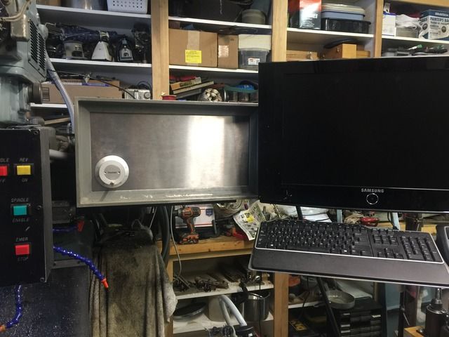
My plan which I know has been done before is to have a panel with the wheel (seen in pic) along with some rotary switches to be able to change from .010/.001" as well as which axis is selected. I'd also like a speed and feed override to be selectable as well. One piece at a time so sorting through the pulse encoder wheel first.
My plan which I know has been done before is to have a panel with the wheel (seen in pic) along with some rotary switches to be able to change from .010/.001" as well as which axis is selected. I'd also like a speed and feed override to be selectable as well. One piece at a time so sorting through the pulse encoder wheel first.
Please Log in or Create an account to join the conversation.
- Dale Lusby
- Offline
- Senior Member
-
Less
More
- Posts: 50
- Thank you received: 2
07 Mar 2016 19:32 #71179
by Dale Lusby

Replied by Dale Lusby on topic Is this Jog Wheel Compatible
Please Log in or Create an account to join the conversation.
- andypugh
-

- Offline
- Moderator
-

Less
More
- Posts: 19879
- Thank you received: 4643
08 Mar 2016 12:42 #71212
by andypugh
Replied by andypugh on topic Is this Jog Wheel Compatible
What are you connecting it to?
You are unlikely to damage anything by connecting it to 5V and tying all the - pins to your 5V GND.
You are unlikely to damage anything by connecting it to 5V and tying all the - pins to your 5V GND.
Please Log in or Create an account to join the conversation.
- Dale Lusby
- Offline
- Senior Member
-
Less
More
- Posts: 50
- Thank you received: 2
10 Mar 2016 05:17 #71316
by Dale Lusby
Replied by Dale Lusby on topic Is this Jog Wheel Compatible
Currently I have a cheap Sainsmart breakout board but may be upgrading in the near future. So in the case of tying 5v in would the + be to the 12v source and then the positive of the S1/S2 go to the input pins on the board?
Please Log in or Create an account to join the conversation.
- andypugh
-
- Offline
- Moderator
-
Less
More
- Posts: 19879
- Thank you received: 4643
10 Mar 2016 10:02 #71322
by andypugh
I was meaning to connect BoB 5V to the +12V pin on the MPG then connect the A+ and B+ to BoB inputs and all the - pins on the MPG to BoB 0V.
If you look at the board yu should be able to read the opto-coupler part number and the value of the current-limiting resistor. From that (and the datasheet for the opto) yuo can work out if the inputs are 12V safe, if the MPG won't work on 5V
Replied by andypugh on topic Is this Jog Wheel Compatible
Currently I have a cheap Sainsmart breakout board but may be upgrading in the near future. So in the case of tying 5v in would the + be to the 12v source and then the positive of the S1/S2 go to the input pins on the board?
I was meaning to connect BoB 5V to the +12V pin on the MPG then connect the A+ and B+ to BoB inputs and all the - pins on the MPG to BoB 0V.
If you look at the board yu should be able to read the opto-coupler part number and the value of the current-limiting resistor. From that (and the datasheet for the opto) yuo can work out if the inputs are 12V safe, if the MPG won't work on 5V
Please Log in or Create an account to join the conversation.
Time to create page: 0.677 seconds