One Joint multiple Servos possible? 6-Axis Robot Motoman K10s
- xcp92
- Offline
- New Member
-

Less
More
- Posts: 10
- Thank you received: 3
23 Feb 2021 14:12 - 23 Feb 2021 14:13 #199830
by xcp92
One Joint multiple Servos possible? 6-Axis Robot Motoman K10s was created by xcp92
Hello, i´m new to this board so please excuse me if i do something wrong.
Currently i am retrofitting a Motorman K10S 6 - Axis robot. The original controlhardware is gone, i use the original servopacks and servos together with a mesa 7i77 card.
I can control each servo without any problem, encoder feedback works, too. (Using Axis)
Joint0 (S), Joint3 (R), Joint4 ( B ), Joint5 (T) are working, no problem.
But:
Joint1 (L) and Joint2(U) behave different.
I can drive servo Nr.2 (for Joint2) and the arm rotates as expected.
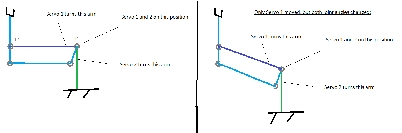
If I want to rotate Joint1 and drive servo Nr.1, Joint1 rotates as expected, but also Joint2, without any movement of servo Nr.2.
This is because of the geometry of the robot (Picture).
When i want to rotate Joint1 only i have to drive servo Nr.1 and 2 simultaneously.
Joint0 -> servo 0
Joint1 -> servo 1 + servo 2
Joint2 -> servo 2
Joint3 -> servo 3
Joint4 -> servo 4
Joint5 -> servo 5
I want to use genserkins to control everything in XYZ and as far as i know for the DH - Parameters each joint has to be directly coupled to one single joint.
How can i do this? Is this even possible in HAL? I tried gantry but i cant connect multiple signals to the analog-output-pin for the servo in HAL.
Thanks in advance
Currently i am retrofitting a Motorman K10S 6 - Axis robot. The original controlhardware is gone, i use the original servopacks and servos together with a mesa 7i77 card.
I can control each servo without any problem, encoder feedback works, too. (Using Axis)
Joint0 (S), Joint3 (R), Joint4 ( B ), Joint5 (T) are working, no problem.
But:
Joint1 (L) and Joint2(U) behave different.
I can drive servo Nr.2 (for Joint2) and the arm rotates as expected.
If I want to rotate Joint1 and drive servo Nr.1, Joint1 rotates as expected, but also Joint2, without any movement of servo Nr.2.
This is because of the geometry of the robot (Picture).
When i want to rotate Joint1 only i have to drive servo Nr.1 and 2 simultaneously.
Joint0 -> servo 0
Joint1 -> servo 1 + servo 2
Joint2 -> servo 2
Joint3 -> servo 3
Joint4 -> servo 4
Joint5 -> servo 5
I want to use genserkins to control everything in XYZ and as far as i know for the DH - Parameters each joint has to be directly coupled to one single joint.
How can i do this? Is this even possible in HAL? I tried gantry but i cant connect multiple signals to the analog-output-pin for the servo in HAL.
Thanks in advance
Last edit: 23 Feb 2021 14:13 by xcp92.
Please Log in or Create an account to join the conversation.
- Aciera
-

- Offline
- Administrator
-

Less
More
- Posts: 4690
- Thank you received: 2098
23 Feb 2021 15:13 #199838
by Aciera
Replied by Aciera on topic One Joint multiple Servos possible? 6-Axis Robot Motoman K10s
That's a tricky one.
"genserkins" uses a modified convention DH-Parameter model as discussed in
"Introduction to Robotics" by John J. Craig. The book can be found online.
In the book (Pages 83 to 89 ) the author shows an example of how to derive the required DH-Parameters for a Yasukawa Motoman L-3 that also has a parallelogram mechanism. Although only a 5-DOF robot you might be able to figure out how to derive the parameters for your robot.
So it seems to be possible to use linuxcnc and genserkins with your type of robot but you will certainly need to invest some serious effort.
The following user(s) said Thank You: Sadmeatball
Please Log in or Create an account to join the conversation.
- Roiki
- Offline
- Premium Member
-

Less
More
- Posts: 116
- Thank you received: 19
23 Feb 2021 16:04 - 23 Feb 2021 16:08 #199843
by Roiki
Replied by Roiki on topic One Joint multiple Servos possible? 6-Axis Robot Motoman K10s
You should be able to connect outputs to multiple inputs. Though I'm not entirely sure if you can connect multiple outputs to one input.
Though what you might require is a custom component or kinematics to calculate the correct motor positions for given movements since your robot is not one motor per axis but requires multiple motor moves for certain axis moves.
It's a bit tricky. First you'd have to figure out what those motor relationships for joint movements are.
Edit: I if the robot uses a differential wrist then there should be a differential component for that.
Last edit: 23 Feb 2021 16:08 by Roiki.
Please Log in or Create an account to join the conversation.
- xcp92
- Offline
- New Member
-
Less
More
- Posts: 10
- Thank you received: 3
23 Feb 2021 19:21 #199880
by xcp92
Replied by xcp92 on topic One Joint multiple Servos possible? 6-Axis Robot Motoman K10s
Thanks for the fast answer.
If Joint1 rotates, the 1 arm rotates around Joint1, but the arm connected to Joint2 stays in the same orientation to ground.
The ratio of both servos is 1:1.
I had calculated the DH - Parameters, but didn´t realised the parallel mechanism. I found the book Aciera mentioned, but i have no idea how to do the calculation for my robot. It seams totally strange ?!.
Its not possible to connect a single output to multiple signals.
Is there a way to do some math in the .hal file?
Or maybe a funktion that can do that?
Please Log in or Create an account to join the conversation.
- tommylight
-

- Away
- Moderator
-

Less
More
- Posts: 21524
- Thank you received: 7338
23 Feb 2021 21:17 #199893
by tommylight
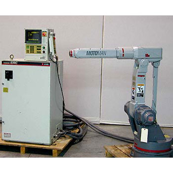
Seems strange to have such a configuration on a 6 axis robot, pretty sure i have never seen one.
Can you take some pictures of the pertaining parts and upload them here, please ?
Replied by tommylight on topic One Joint multiple Servos possible? 6-Axis Robot Motoman K10s
I failed to understand why this?
Joint0 -> servo 0
Joint1 -> servo 1 + servo 2
Joint2 -> servo 2
Joint3 -> servo 3
Joint4 -> servo 4
Joint5 -> servo 5
Seems strange to have such a configuration on a 6 axis robot, pretty sure i have never seen one.
Can you take some pictures of the pertaining parts and upload them here, please ?
Please Log in or Create an account to join the conversation.
- Aciera
-
- Offline
- Administrator
-
Less
More
- Posts: 4690
- Thank you received: 2098
24 Feb 2021 07:42 #199932
by Aciera
Replied by Aciera on topic One Joint multiple Servos possible? 6-Axis Robot Motoman K10s
Axis coupling is mostly used in palletizing (I think). Here is good explanation:
robodk.com/blog/robot-axis-coupling/
robodk.com/blog/robot-axis-coupling/
Please Log in or Create an account to join the conversation.
- xcp92
- Offline
- New Member
-
Less
More
- Posts: 10
- Thank you received: 3
24 Feb 2021 11:28 #199957
by xcp92
Replied by xcp92 on topic One Joint multiple Servos possible? 6-Axis Robot Motoman K10s
I made a quick sketch with paint to illustrate the kinematic problem .
After some reading in this forum and some tinkering with the hal component generator i made a custom hal component that can redirect the signals to the servos. Tomorrow i will try it out if this works.
After some reading in this forum and some tinkering with the hal component generator i made a custom hal component that can redirect the signals to the servos. Tomorrow i will try it out if this works.
Attachments:
Please Log in or Create an account to join the conversation.
- xcp92
- Offline
- New Member
-
Less
More
- Posts: 10
- Thank you received: 3
01 Dec 2021 19:48 - 01 Dec 2021 19:53 #228148
by xcp92
Replied by xcp92 on topic One Joint multiple Servos possible? 6-Axis Robot Motoman K10s
Here is the working fix:
Custom component that redirects the signals so that only one joint moves:
These are the relevant parts from the hal file:
This works flawlessly so far. Hope this helps.
Custom component that redirects the signals so that only one joint moves:
component motomanfix "Fix for Motoman K10S";

pin in float j2_fb_in;
pin in float j1_pos_cmd_in;
pin in float j2_pos_cmd_in;
pin out float j2_cmd_topid_out;
pin out float j2_fb_tojoint_out;

variable float j1_pos_cmd_base = 0;

function _ fp;

author "Xcp92";
license "GPL";

;;

FUNCTION(_)
{
if(j1_pos_cmd_base == 0) j1_pos_cmd_base = j1_pos_cmd_in;
j2_cmd_topid_out = j2_pos_cmd_in + (j1_pos_cmd_in - j1_pos_cmd_base);
j2_fb_tojoint_out = j2_fb_in - (j1_pos_cmd_in - j1_pos_cmd_base);
}
These are the relevant parts from the hal file:
loadrt motomanfix
addf motomanfix.0               servo-thread

net j1-pos-cmd            <=  joint.1.motor-pos-cmd
net j1-pos-cmd            =>  pid.j1.command
net j1-pos-cmd             =>  motomanfix.0.j1-pos-cmd-in

net j2-pos-cmd       <=  joint.2.motor-pos-cmd
net j2-pos-cmd       =>  motomanfix.0.j2-pos-cmd-in

net j2-cmd-topid     <=  motomanfix.0.j2-cmd-topid-out
net j2-cmd-topid     =>  pid.j2.command

net j2-pos-fb        <=  hm2_5i25.0.encoder.02.position
net j2-pos-fb         =>  motomanfix.0.j2-fb-in
net j2-pos-fb        =>  pid.j2.feedback

net j2-pos-fb-tojoint  <=  motomanfix.0.j2-fb-tojoint-out
net j2-pos-fb-tojoint  =>  joint.2.motor-pos-fb
This works flawlessly so far. Hope this helps.
Last edit: 01 Dec 2021 19:53 by xcp92.
The following user(s) said Thank You: Aciera
Please Log in or Create an account to join the conversation.
- Grotius
-

- Offline
- Platinum Member
-

Less
More
- Posts: 2419
- Thank you received: 2348
02 Dec 2021 02:13 #228169
by Grotius
Replied by Grotius on topic One Joint multiple Servos possible? 6-Axis Robot Motoman K10s
Hi,
It looks like a normal robot. The kinematic model of a 6 axis robot can be used. Only 2 Joints need a tiny calculation to
get the desired position.
Is there a way to do some math in the .hal file?
I think not. a .hal file is just a text file.
Here is a hal component for robot kinematics : github.com/grotius-cnc/hal-kinematics
It is recently updated. This can do the kinematic calculations for you.
In the halmodule.c function "write pins" you can add the tiny calculation for the combined joints if you want to.
The following user(s) said Thank You: Sadmeatball
Please Log in or Create an account to join the conversation.
Time to create page: 0.111 seconds