Hal gearchange for beginner
- greg23_78
- Offline
- Premium Member
-

- Posts: 142
- Thank you received: 7
I am more at ease with graphical programming than with lines of code, so I have tried to translate the andypugh code to understand it better. Below is the andypugh code
loadusr -W hy_vfd -d /dev/ttyUSB0
loadrt gearchange
addf gearchange.0 servo-thread
setp gearchange.0.max-low 500
setp gearchange.0.high-ratio 1
setp gearchange.0.low-ratio 3
setp gearchange.0.brake-enable 0

setp   pid.s.Pgain     [SPINDLE_9]P
setp   pid.s.Igain     [SPINDLE_9]I
setp   pid.s.Dgain     [SPINDLE_9]D
setp   pid.s.bias      [SPINDLE_9]BIAS
setp   pid.s.FF0       [SPINDLE_9]FF0
setp   pid.s.FF1       [SPINDLE_9]FF1
setp   pid.s.FF2       [SPINDLE_9]FF2
setp   pid.s.deadband  [SPINDLE_9]DEADBAND
setp   pid.s.maxoutput [SPINDLE_9]MAX_OUTPUT
setp   pid.s.error-previous-target true
setp   pid.s.maxerror .0005

net spindle-index-enable  <=> pid.s.index-enable
net spindle-enable        =>  pid.s.enable
net spindle-vel-cmd-rpm     => pid.s.command
net spindle-vel-fb-rpm      => pid.s.feedback
net spindle-output        <=  pid.s.output

# ---Encoder feedback signals/setup---

net spindle-revs             <=   hm2_5i24.0.resolver.04.position
net spindle-vel-fb-rps       <=   hm2_5i24.0.resolver.04.velocity
net spindle-index-enable     <=>  hm2_5i24.0.resolver.04.index-enable

# ---setup spindle control signals---

net spindle-vel-cmd-rps        <=  motion.spindle-speed-out-rps
net spindle-vel-cmd-rps-abs    <=  motion.spindle-speed-out-rps-abs
net spindle-vel-cmd-rpm        <=  motion.spindle-speed-out
net spindle-vel-cmd-rpm-abs    <=  motion.spindle-speed-out-abs
net spindle-enable             <=  motion.spindle-on
net spindle-cw                 <=  motion.spindle-forward
net spindle-ccw                <=  motion.spindle-reverse
net spindle-brake              <=  motion.spindle-brake
net spindle-revs               =>  motion.spindle-revs
net spindle-at-speed           =>  motion.spindle-at-speed
net spindle-vel-fb-rps         =>  motion.spindle-speed-in
net spindle-index-enable      <=>  motion.spindle-index-enable

# ---Connect the VFD---

net spindle-at-speed hy_vfd.spindle-at-speed

net machine.on.delayed hy_vfd.enable

net spindle-enable hy_vfd.spindle-on gearchange.0.spindle-on
net spindle-cw hy_vfd.spindle-forward
net spindle-ccw hy_vfd.spindle-reverse
net spindle-vel-cmd-rpm-abs gearchange.0.speed-command
net manual-low gearchange.0.manual-low <=
net manual-high gearchange.0.manual-high <=
net motor-speed gearchange.0.motor-speed => hy_vfd.speed-command

net low-gear gearchange.0.low-gear => hm2_7i84.008a.output-11
net high-gear gearchange.0.high-gear => hm2_7i84.008a.output-10
net brake gearchange.0.brake => hm2_7i84.008a.output-12
Here is what I tried to transcribe.
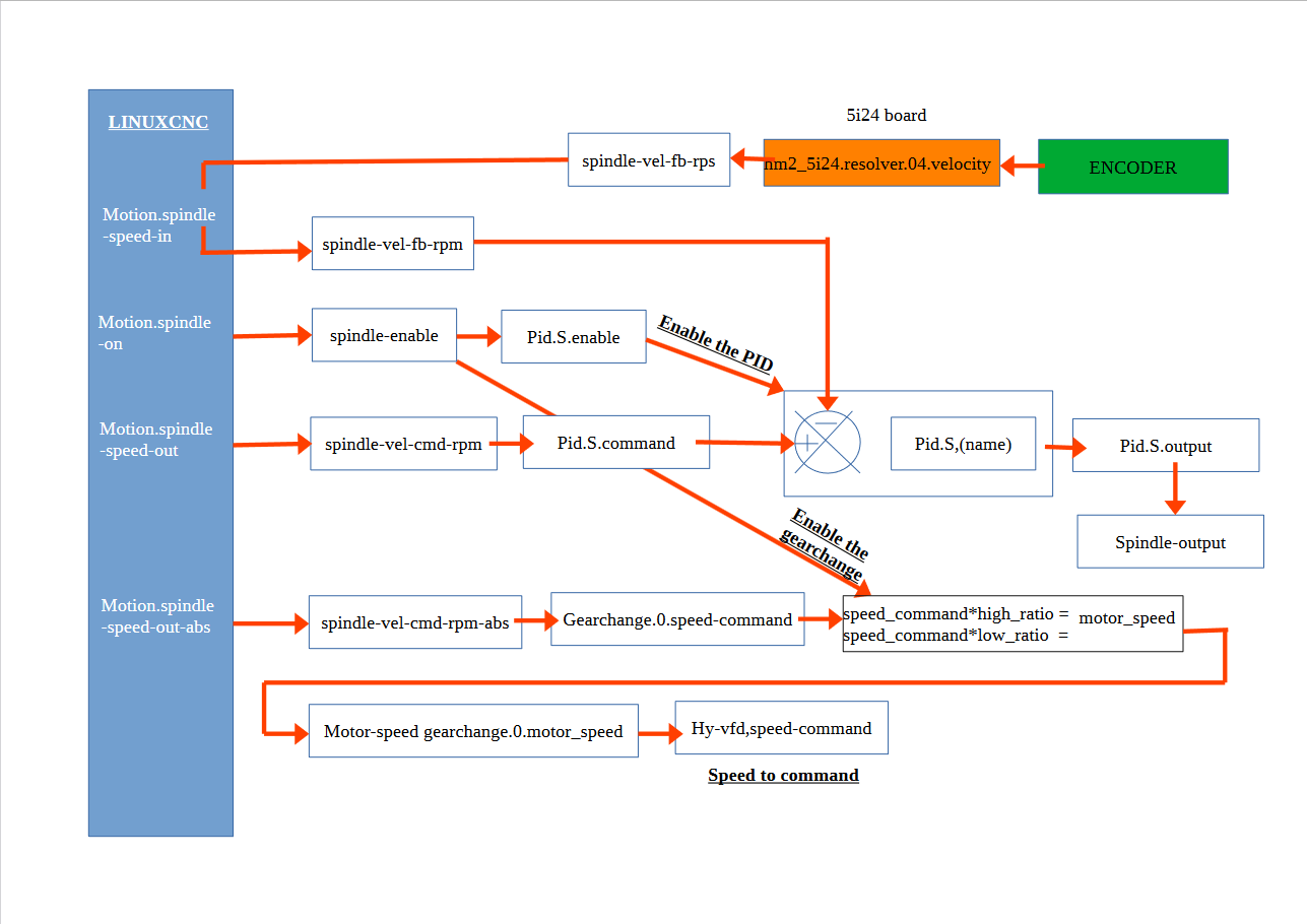
My problem is that I can't understand the connection between the spindle-output signal and the hy-vfd.speed signal because one manages the speed change and the other the pid command. .
Do they have a connection that I don't know about or do these two signals have a different function?
Attachments:
Please Log in or Create an account to join the conversation.
- blazini36
- Offline
- Platinum Member
-

- Posts: 972
- Thank you received: 167
If the VFD needs the to be feed by an always-positive number use tha "abs" component after the "spindle-output" signal. Then remove the spindle-vel-cmd-rpm-abs signal and put the signal off the "abs" component in it's place to connect the PID to gearchange.0.speed-command.
You might want to do something to switch PID parameters depending on what gear you are in. I setup a gearchange on a servo spindle years ago before the gearchange component was available. It's not too bad if your encoder is on your spindle. If your encoder is on the motor like mine then you have to scale that feedback as well. I've got mux's, scales, and gates all over my spindle section.
Please Log in or Create an account to join the conversation.
- greg23_78
- Offline
- Premium Member
-
- Posts: 142
- Thank you received: 7
i think i have the same machine setup as you. the VFD 0-10V will control a servo spindle (japanese spindle) with an integer encoder in the spindle.
my intention for the machine
1) to run my VFD in open loop (I understand that tuning a spindle is tricky)
2) Orient my spindle to change tool (with encoder or proximity sensor) the simplest for the moment being a beginner.
3)classic ladder for the tool change system
4) after some experience with linuxcnc go to closed loop
for your spindle, do you use mux and gates components for the orientation of your spindle (tool change) or for the rotation of the spindle ?
I have modified the diagram according to your feedback to recover only positive values. I know that in open loop I don't need PID but I would like to prepare for the servo control afterwards.
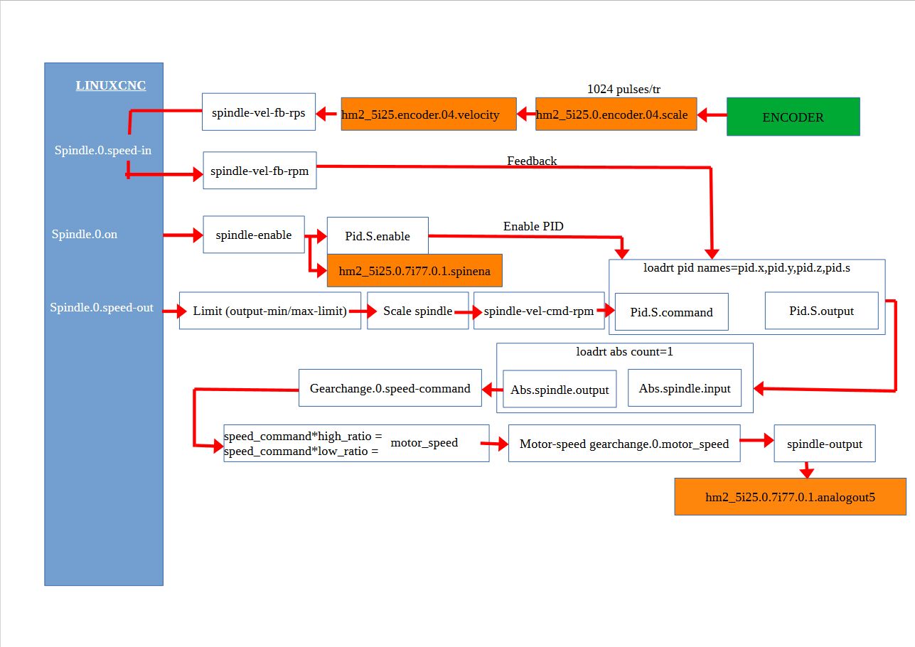
Can spindle-out work if PID.S.enable is false?
Attachments:
Please Log in or Create an account to join the conversation.
- blazini36
- Offline
- Platinum Member
-
- Posts: 972
- Thank you received: 167
Mine is quite different. I have an AC servo belt driving the spindle, the encoder is the motor so I have to scale the feedback and command to effect the spindle. I control the servo with step/direction which puts the drive in position mode vs speed mode if I were using 0-10vthank you blazini for your feedback,
i think i have the same machine setup as you. the VFD 0-10V will control a servo spindle (japanese spindle) with an integer encoder in the spindle.
I don't do any spindle orientation because I don't have a toolchanger. I probably wouldn't bother if I did since none of my tools would need to be oriented but I could if I really wanted to. I do have a proximity switch on my spindle so LinuxCNC gets an index directly from the spindle for rigid tapping. All the Mux's and stuff basically do what your gearchange component does, it wasn't available back then. I also have to "gearchange" the position feedback since the estimated position of the spindle in a non 1:1 gear will be different from the servo's encoder feedback. If you did run in position mode you could just use multiple gearchange components to scale the position as well, not just the speed command.for your spindle, do you use mux and gates components for the orientation of your spindle (tool change) or for the rotation of the spindle ?
Tuning the PID for a spindle seems like it would be tricky and maybe it is sometimes but Servo drives run their own internal PID. I'd always intended to mux the LinuxCNC PID settings to switch for a gearchange but just to get it running I never connected the LinuxCNC PID. The spindle has always ran fine so I never bothered. If you're using an AC induction motor that has a rotor with some mass, tuning the PID should not be difficult. My servo has low inertia so it would be affected much more from the shock of cutting air and then entering a cut servo drives themselves respond much quicker than VFDs (typically) so it's not really a problem.
I'm not sure, according to the docs:pid.N.enable bit inWhen true, enables the PID calculations. When false, output is zero, and all internal integrators, etc, are reset.In which case no. Off the top of my head I'm not sure if that's the case but you can test this by setting it all up with the PID and toggling the enable bit, if the output is 0 it's not going to work but if the output is just a passthrough for the input then yeah. If the output is 0 from disable you can just leave the PID enabled and feed all of the PID parameters with a muxes. Instead of toggling the PID enable, you would toggle the mux select bits. If you set one mux input to the desired PID value, then set the other to 0 toggling the select bit will either pass the value or 0 to the PID parameter input. If the parameter input is 0 it is null so if you set the P,I,D to 0 it should just pass through the input.Can spindle-out work if PID.S.enable is false?
Please Log in or Create an account to join the conversation.
- greg23_78
- Offline
- Premium Member
-
- Posts: 142
- Thank you received: 7
I would like to know how you have configured the vfd and pid parameters of your spindle, can you share your config?.
with my experience on hobby cnc, you have to set the vfd according to the motor rotation frequency/speed, with a servomotor do you have to follow this rule? because i have no indication on my servomotor.
Is the PID configuration identical to the PID Tuning procedure like my axes?
Please Log in or Create an account to join the conversation.
- blazini36
- Offline
- Platinum Member
-
- Posts: 972
- Thank you received: 167
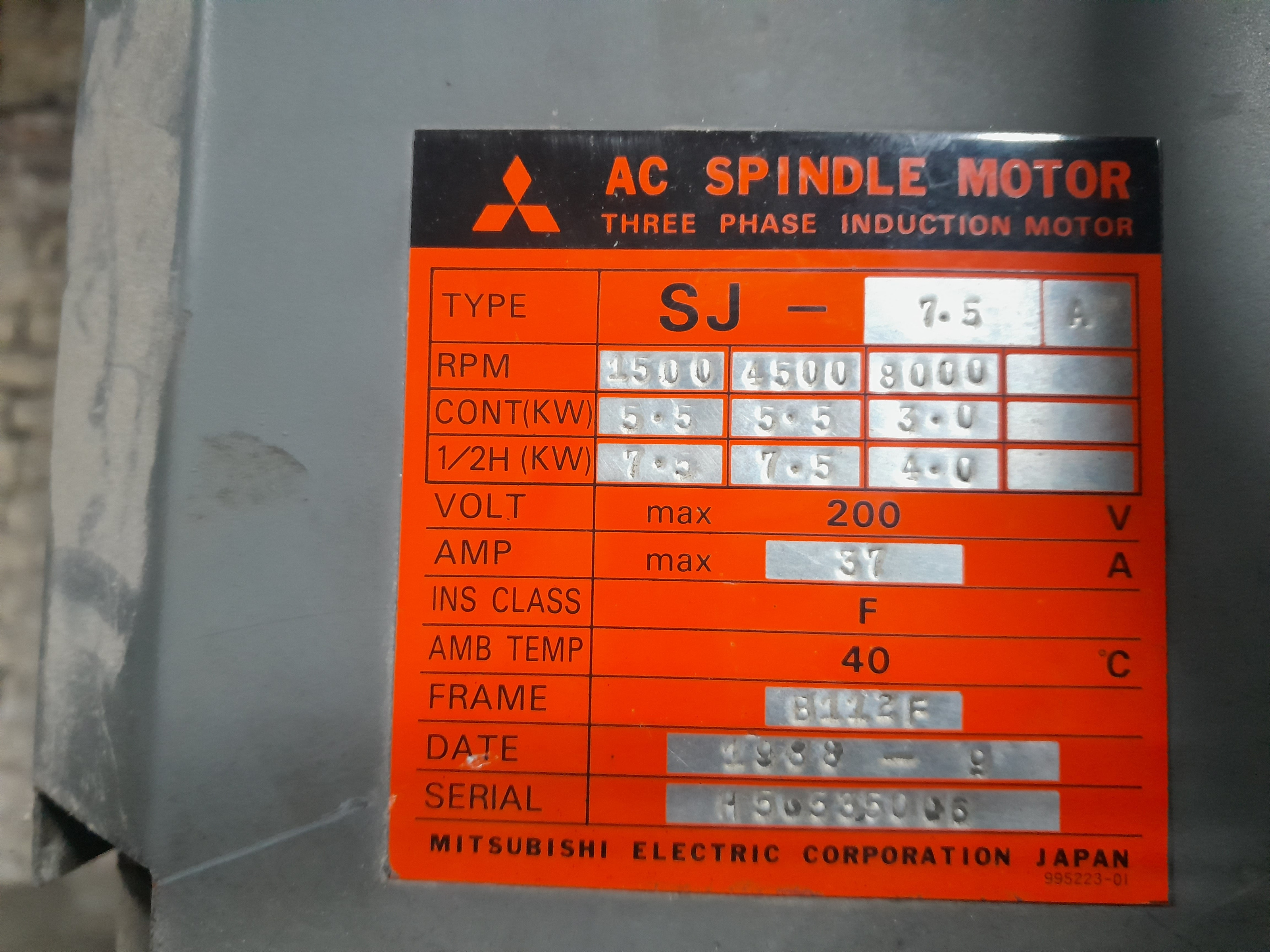
Like I said above, I run an AC servo, not a VFD and I do not use a PID for the spindle in LinuxCNC. Did you try to configure and run this?my spindle system also has belts like the attached photo.
I would like to know how you have configured the vfd and pid parameters of your spindle, can you share your config?.
with my experience on hobby cnc, you have to set the vfd according to the motor rotation frequency/speed, with a servomotor do you have to follow this rule? because i have no indication on my servomotor.
Is the PID configuration identical to the PID Tuning procedure like my axes?
Please Log in or Create an account to join the conversation.
- greg23_78
- Offline
- Premium Member
-
- Posts: 142
- Thank you received: 7
but i've tried to get the gearchange to work but i'm having problems declaring variables or pins. below is my hal and ini
--------------------------------------------------------------------------
INI
--------------------------------------------------------------------------
P = 0.0
I = 0.0
D = 0.0
FF0 = 1.0
FF1 = 0.0
FF2 = 0.0
BIAS = 0.0
DEADBAND = 0.0
MAX_OUTPUT = 3000.0
ENCODER_SCALE = 1024.0
OUTPUT_SCALE = 1500
OUTPUT_MIN_LIMIT = 0
OUTPUT_MAX_LIMIT = 1500
------------------------------------------------------------------------------
HAL
------------------------------------------------------------------------------
loadrt abs count=1
loadrt gearchange

addf abs.0 servo-thread
addf gearchange.0 servo-thread
setp gearchange.0.max-low 400
setp gearchange.0.high-ratio 1
setp gearchange.0.low-ratio 2
setp gearchange.0.brake-enable 0

#*******************
#  SPINDLE
#*******************

setp   pid.s.Pgain     [SPINDLE_0]P
setp   pid.s.Igain     [SPINDLE_0]I
setp   pid.s.Dgain     [SPINDLE_0]D
setp   pid.s.bias      [SPINDLE_0]BIAS
setp   pid.s.FF0       [SPINDLE_0]FF0
setp   pid.s.FF1       [SPINDLE_0]FF1
setp   pid.s.FF2       [SPINDLE_0]FF2
setp   pid.s.deadband  [SPINDLE_0]DEADBAND
setp   pid.s.maxoutput [SPINDLE_0]MAX_OUTPUT
setp   pid.s.error-previous-target true


net spindle-index-enable  <=> pid.s.index-enable
net spindle-enable        =>  pid.s.enable
net spindle-vel-cmd-rpm     => pid.s.command
net spindle-vel-fb-rpm      => pid.s.feedback
net abs.0.in               <=  pid.s.output
net positive-only-spindle-speed-cmd  <= abs.0.out


# ---PWM Generator signals/setup---

setp   hm2_5i25.0.7i77.0.1.analogout5-scalemax  [SPINDLE_0]OUTPUT_SCALE
setp   hm2_5i25.0.7i77.0.1.analogout5-minlim    [SPINDLE_0]OUTPUT_MIN_LIMIT
setp   hm2_5i25.0.7i77.0.1.analogout5-maxlim    [SPINDLE_0]OUTPUT_MAX_LIMIT

# ---Encoder feedback signals/setup---

setp    hm2_5i25.0.encoder.05.counter-mode 0
setp    hm2_5i25.0.encoder.05.filter 1
setp    hm2_5i25.0.encoder.05.index-invert 0
setp    hm2_5i25.0.encoder.05.index-mask 0
setp    hm2_5i25.0.encoder.05.index-mask-invert 0
setp    hm2_5i25.0.encoder.05.scale  [SPINDLE_0]ENCODER_SCALE


net spindle-revs             <=   hm2_5i24.0.resolver.05.position
net spindle-vel-fb-rps       <=   hm2_5i24.0.resolver.05.velocity
net spindle-index-enable     <=>  hm2_5i24.0.resolver.05.index-enable

# ---setup spindle control signals---

net spindle-vel-cmd-rps        <=  spindle.0.speed-out-rps
net spindle-vel-cmd-rps-abs    <=  spindle.0.speed-out-rps-abs
net spindle-vel-cmd-rpm        <=  spindle.0.speed-out
net spindle-vel-cmd-rpm-abs    <=  spindle.0.speed-out-abs
net spindle-enable             <=  spindle.0.spindle-on
net spindle-cw                 <=  spindle.0.spindle-forward
net spindle-ccw                <=  spindle.0.spindle-reverse
net spindle-brake              <=  spindle.0.spindle-brake
net spindle-revs               =>  spindle.0.spindle-revs
net spindle-at-speed           =>  spindle.0.spindle-at-speed
net spindle-vel-fb-rps         =>  spindle.0.spindle-speed-in
net spindle-index-enable      <=>  spindle.0.spindle-index-enable

# ---Connect the VFD---

net positive-only-spindle-speed-cmd => gearchange.0.speed-command
net motor-speed gearchange.0.motor-speed => hm2_5i25.0.7i77.0.1.analogout5
net spindle-enable => gearchange.0.spindle-on => hm2_5i25.0.7i77.0.1.spinena
net spindle-cw  => hm2_5i25.0.7i77.0.0.output-10
net spindle-ccw  => hm2_5i25.0.7i77.0.0.output-09
net low-gear gearchange.0.low-gear => hm2_5i25.0.7i77.0.0.output-11
net high-gear gearchange.0.high-gear => hm2_5i25.0.7i77.0.0.output-12
net brake gearchange.0.brake => hm2_5i25.0.7i77.0.0.output-13
#net manual-low gearchange.0.manual-low <=
#net manual-high gearchange.0.manual-high <=
#net spindle-at-speed
et le fichier gearchange.comp de andypugh
component gearchange "A component to choose spindle gears according to spindle speed";
pin in float speed-command;
pin in bit spindle-on;
pin in bit manual-low;
pin in bit manual-high;
pin in bit brake-enable;
pin out float motor-speed;
pin out bit low-gear;
pin out bit high-gear;
pin out bit brake;
param rw float low-ratio=3;
param rw float high-ratio=1;
param rw float max-low = 500;

author "andy pugh";
license "GPL";
function _;

;;

FUNCTION(_){
    static int old_M3;

    if (spindle_on) {
        if (!old_M3){ // spindle off to on transition
            if (manual_high) {
                high_gear = 1;
                low_gear = 0;
                brake = 0;
            }
            else if (manual_low){
                high_gear = 0;
                low_gear = 1;
                brake = 0;
            } else if (speed_command <= max_low){
                high_gear = 0;
                low_gear = 1;
                brake = 0;
            } else {
                high_gear = 1;
                low_gear = 0;
                brake = 0;
            }
        }
    } else { //spindle off
        high_gear = 0;
        low_gear = 0;
        brake = brake_enable;
    }

    old_M3 = spindle_on;

    if (high_gear){
        motor_speed = speed_command * high_ratio;
    } else if (low_gear){
        motor_speed = speed_command * low_ratio;
    }
}
I get the following error message : parameter or pin "gearchange.0.max-low" not found
"gearchange.0.high-ratio"
"gearchange.0.low-ratio"
"gearchange.0.brake-enable "
what do I need to add to declare these parameters?
Please Log in or Create an account to join the conversation.
- Aciera
-

- Offline
- Administrator
-

- Posts: 4689
- Thank you received: 2097
Please Log in or Create an account to join the conversation.
- greg23_78
- Offline
- Premium Member
-
- Posts: 142
- Thank you received: 7
sudo halcompile --install gearchange.compI have a question about programming on the HAL file.
I've had several errors with the abs component. Why are these program lines is wrong?
loardt abs count=1
addf abs.0 servo-thread

net spindle-vel-cmd-rpm     <= spindle.0.speed-out
net spindle-vel-cmd-rpm     => pid.s.command
net abs.0.in         <=  pid.s.output
net positive-only-spindle-speed-cmd <= abs.0.out
net positive-only-spindle-speed-cmd => gearchange.0.speed-command
I succeeded using the code below but how could I have made my code above work?
net spindle-vel-cmd-rpm-abs    <=  spindle.0.speed-out-abs
net spindle-vel-cmd-rpm-abs     => pid.s.command
net spindle-output          <=  pid.s.output
net spindle-output => gearchange.0.speed-commandPlease Log in or Create an account to join the conversation.
- Aciera
-
- Offline
- Administrator
-
- Posts: 4689
- Thank you received: 2097
If that is not it then it would help a lot to know what the actual error was.
Please Log in or Create an account to join the conversation.