Physical safety relay and software estop latch working together?
- thomaseg
- Offline
- Senior Member
-

Less
More
- Posts: 44
- Thank you received: 5
25 Dec 2024 21:44 - 25 Dec 2024 21:48 #317376
by thomaseg
Physical safety relay and software estop latch working together? was created by thomaseg
Hi,
I've been spending the last couple of days trying to figure out how to make the "software estop" work together with my safety relay. But i'm going in circles and i need a kick from someone, maybe you?
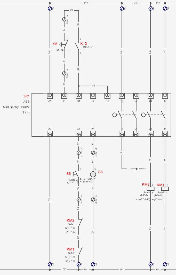
First off, i have this physical circuit to handle the emergency stop logic in hardware:
...the idea is that estop should work without any software involvement. And everything should be as redundant as could be. I have dual (safety) contactors(KM1 + KM2) that cuts power to all drives and at the same time prevents resetting the estop-circuit in cause of failure. I have a proper estop-button(it's redundant contacts, but only shown as one here in S5). On top of that i have added an inline relay, K13, which can be triggered by software, aswell as the wire "1" which goes to an input in LinuxCNC in order to tell it the state of the safety relay. There is a short delay(~0,5sec) between the two sets of relays in the safety relay, so ideally the signal to LinuxCNC should be able to tell the servos to emergency stop just before the power is killed.
So far, so good. Everything works just like i want it. The latching works excellent and the signals to and from LinuxCNC also works as expected....
However, i'm totally going in circles when i try to add an estop latch inside LinuxCNC to work in conjunction with the hardware safety relay. I took inspiration from a thread from the user Unlogic who seem to have it working. But i end up having a latch #1 that depends on latch #2 that depends on latch #1 again....ehh... so currently i'm just having the inputs tied into LinuxCNC like this:
..this "sorta works" and prevents anything powering on before LinuxCNC has booted properly. However the UI experience is kinda bad as i have to press a button extra and there is not really any feedback to the user 
SO, the question: Has anyone got a combination of a physical safetyrelay and an estop latch to work "like it should"? I'd be very interested in seeing how others have solved this issue...
/Thomas
I've been spending the last couple of days trying to figure out how to make the "software estop" work together with my safety relay. But i'm going in circles and i need a kick from someone, maybe you?
First off, i have this physical circuit to handle the emergency stop logic in hardware:
...the idea is that estop should work without any software involvement. And everything should be as redundant as could be. I have dual (safety) contactors(KM1 + KM2) that cuts power to all drives and at the same time prevents resetting the estop-circuit in cause of failure. I have a proper estop-button(it's redundant contacts, but only shown as one here in S5). On top of that i have added an inline relay, K13, which can be triggered by software, aswell as the wire "1" which goes to an input in LinuxCNC in order to tell it the state of the safety relay. There is a short delay(~0,5sec) between the two sets of relays in the safety relay, so ideally the signal to LinuxCNC should be able to tell the servos to emergency stop just before the power is killed.
So far, so good. Everything works just like i want it. The latching works excellent and the signals to and from LinuxCNC also works as expected....
However, i'm totally going in circles when i try to add an estop latch inside LinuxCNC to work in conjunction with the hardware safety relay. I took inspiration from a thread from the user Unlogic who seem to have it working. But i end up having a latch #1 that depends on latch #2 that depends on latch #1 again....ehh... so currently i'm just having the inputs tied into LinuxCNC like this:
net estop-loopout iocontrol.0.emc-enable-in    <= lcec.0.DI1.din-0     # This is the signal from wire "1"
net estop-relay iocontrol.0.user-enable-out => lcec.0.DO1.dout-3 # This is relay K13SO, the question: Has anyone got a combination of a physical safetyrelay and an estop latch to work "like it should"? I'd be very interested in seeing how others have solved this issue...
/Thomas
Attachments:
Last edit: 25 Dec 2024 21:48 by thomaseg.
Please Log in or Create an account to join the conversation.
- rodw
-

- Away
- Platinum Member
-

Less
More
- Posts: 11649
- Thank you received: 3921
26 Dec 2024 05:22 #317388
by rodw
Replied by rodw on topic Physical safety relay and software estop latch working together?
iocontrol.0.user-request-enable can be used as an estop reset signal (eg in place of S6). A short pulse is sent on this output for this purpose. I chose to just stick with the external reset button and connect to iocontrol.0.emc-enable-in, I used a relay on your S6 circuit to do this
If you want an internal estop and an external estop, multiple instances of estop-latch component should let you do this.
If you want an internal estop and an external estop, multiple instances of estop-latch component should let you do this.
Attachments:
Please Log in or Create an account to join the conversation.
- Benb
-

- Offline
- Elite Member
-

Less
More
- Posts: 183
- Thank you received: 60
27 Dec 2024 01:10 #317448
by Benb
Replied by Benb on topic Physical safety relay and software estop latch working together?
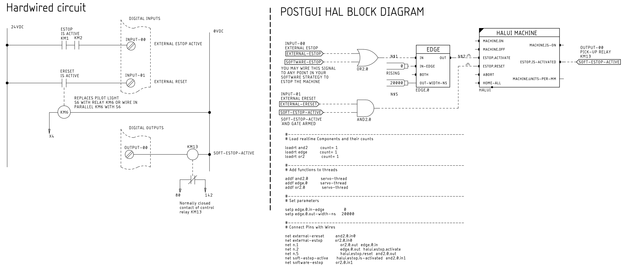
The hardwired diagram shows two normally open contacts in series KM1 AND KM2 indicating that the Estop is active. The rest of the circuit is similar to what you had in mind. Please do not add a screen (UI) estop or reset buttons; make it a habit to only use the external hardwired estop and reset push buttons otherwise you defeat the use of a safety system. The hal block diagram I use it to generate the hal file but it might help you understand what the hal net file does.
#
# Load realtime Components and their counts
loadrt and2 count= 1
loadrt edge count= 1
loadrt or2 count= 1
#
# Add functions to threads
addf and2.0 servo-thread
addf or2.0 servo-thread
addf edge.0 servo-thread
#
# Set parameters
setp edge.0.in-edge 0
setp edge.0.out-width-ns 20000
#
# Connect Pins with Wires
net external-ereset and2.0.in0
net external-estop or2.0.in0
net n.1 or2.0.out edge.0.in
net n.2 edge.0.out halui.estop.activate
net n.5 halui.estop.reset and2.0.out
net soft-estop-active halui.estop.is-activated and2.0.in1
net software-estop or2.0.in1
#
# Load realtime Components and their counts
loadrt and2 count= 1
loadrt edge count= 1
loadrt or2 count= 1
#
# Add functions to threads
addf and2.0 servo-thread
addf or2.0 servo-thread
addf edge.0 servo-thread
#
# Set parameters
setp edge.0.in-edge 0
setp edge.0.out-width-ns 20000
#
# Connect Pins with Wires
net external-ereset and2.0.in0
net external-estop or2.0.in0
net n.1 or2.0.out edge.0.in
net n.2 edge.0.out halui.estop.activate
net n.5 halui.estop.reset and2.0.out
net soft-estop-active halui.estop.is-activated and2.0.in1
net software-estop or2.0.in1
Attachments:
Please Log in or Create an account to join the conversation.
- thomaseg
- Offline
- Senior Member
-

Less
More
- Posts: 44
- Thank you received: 5
28 Dec 2024 09:19 #317540
by thomaseg
I'm not 100% sure the above diagram will work exactly like this with my setup, however your input sparked an idea to solve my "circular dependency" problem between the software and hardware latches: I need to use a "oneshot"-component to connect the two latches instead of connecting them directly(and thereby creating the problematic circular dependency). Sounds obvious now, not sure why i didn't see that option the other day. So thanks for the input, i think i have a viable way to solve this now!
Thanks!
Replied by thomaseg on topic Physical safety relay and software estop latch working together?
I like your diagrams, what do you use to make them?The hardwired diagram shows two normally open contacts in series KM1 AND KM2 indicating that the Estop is active. The rest of the circuit is similar to what you had in mind. Please do not add a screen (UI) estop or reset buttons; make it a habit to only use the external hardwired estop and reset push buttons otherwise you defeat the use of a safety system. The hal block diagram I use it to generate the hal file but it might help you understand what the hal net file does.
I'm not 100% sure the above diagram will work exactly like this with my setup, however your input sparked an idea to solve my "circular dependency" problem between the software and hardware latches: I need to use a "oneshot"-component to connect the two latches instead of connecting them directly(and thereby creating the problematic circular dependency). Sounds obvious now, not sure why i didn't see that option the other day. So thanks for the input, i think i have a viable way to solve this now!
Thanks! I couldn't wrap my head around this at first, but i think i got the gist of it now. I'll try to implement this short pulse and post the solution here for future reference.rodw post=317388 userid=20660
iocontrol.0.user-request-enable can be used as an estop reset signal (eg in place of S6). A short pulse is sent on this output for this purpose. I chose to just stick with the external reset button and connect to iocontrol.0.emc-enable-in, I used a relay on your S6 circuit to do this
Thanks!
The following user(s) said Thank You: rodw
Please Log in or Create an account to join the conversation.
- Benb
-

- Offline
- Elite Member
-

Less
More
- Posts: 183
- Thank you received: 60
29 Dec 2024 04:18 #317590
by Benb
Replied by Benb on topic Physical safety relay and software estop latch working together?
Hi Thomas,
For the block diagram conversion to Hal netlisting I use Eagle2hal its documentated in lthe inuxcnc wiki (old but works for me). However if I had to start again I would learn Ed Nisley's Kicad to HAL the source code is in Python also the Kicad people are planning to release a schematic API in their next release this would make it easy to make run time changes to the schematic capture and animate the schematic with realtime values.
gist.github.com/ednisley/cd69ad5a899226067d7a4a92c2114568
Please Log in or Create an account to join the conversation.
Time to create page: 0.119 seconds


