Hal configuration for BISS encoder
- pmchetan
- Offline
- Senior Member
-

Less
More
- Posts: 58
- Thank you received: 3
13 Feb 2025 01:37 #321404
by pmchetan
Replied by pmchetan on topic Hal configuration for BISS encoder
I wanted to verify the motor controls with PWM with motor disassembled from the axis with no encoder feedback, just motor rotation and direction of the spin. Is it possible to have a minimal HAL setup where I can load the driver and check the motor in open loop also note down all the pin names and parameters names that the driver assigns so that I could build the complete HAL better?
Please Log in or Create an account to join the conversation.
- PCW
-

- Away
- Moderator
-

Less
More
- Posts: 17955
- Thank you received: 5262
13 Feb 2025 01:57 #321405
by PCW
Replied by PCW on topic Hal configuration for BISS encoder
If you run a normal LinuxCNC hal file (with no PWM support/connections),
you can do this from the watch dialog:
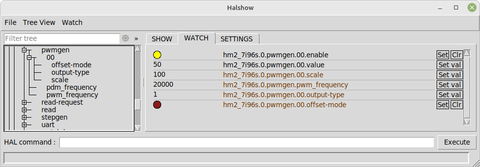
20KHZ PWM enabled and set to 50%
you can do this from the watch dialog:
20KHZ PWM enabled and set to 50%
Attachments:
Please Log in or Create an account to join the conversation.
- pmchetan
- Offline
- Senior Member
-
Less
More
- Posts: 58
- Thank you received: 3
13 Feb 2025 11:18 - 13 Feb 2025 12:29 #321432
by pmchetan
Replied by pmchetan on topic Hal configuration for BISS encoder
In many HostMot2 firmware builds the PWM frequency isn’t a runtime‐adjustable parameter. Typically the pwmgen component would export a parameter called either “pwm_frequency” or “pwm-freq” to let you set the carrier frequency, but in your firmware configuration only the two basic pins (enable and value) are exported. This means that the PWM frequency is fixed by the bitfile you flashed.
To change the frequency at runtime you would need to use (or build) a firmware configuration that exports that parameter.
PWM mode selected on the drive, I can switch the SV pin to COM with hand and the motor spins. Suspect is that the 7i76 generated 20 kiloherts PWM signal is too high for the drive to handle. So runtime frequency option is needed so that I can choose in HAL file. This was what I was referring to in my last post, I assumed all possible pin names will all be listed somewhere but I guess those need to be made available by the firmware. Can you included everything to be exposed at runtime: we can use what is needed and ignore the rest right?
Also I wanted to ask the .vhd file you gave is it the complete firmware design files that can be compiled into a bit file in suitable version of xilinx ISE?
Last edit: 13 Feb 2025 12:29 by pmchetan. Reason: Added extra context.
Please Log in or Create an account to join the conversation.
- PCW
-
- Away
- Moderator
-
Less
More
- Posts: 17955
- Thank you received: 5262
13 Feb 2025 15:19 - 13 Feb 2025 15:45 #321443
by PCW
Replied by PCW on topic Hal configuration for BISS encoder
In many HostMot2 firmware builds the PWM frequency isn’t a runtime‐adjustable parameter. Typically the pwmgen component would export a parameter called either “pwm_frequency” or “pwm-freq” to let you set the carrier frequency, but in your firmware configuration only the two basic pins (enable and value) are exported. This means that the PWM frequency is fixed by the bitfile you flashed.
That's not true, all hostmot2 firmware with a PWMgens exports pwm_frequency and pdm_frequency parameters. Note that these are parameters, not pins.
Also I wanted to ask the .vhd file you gave is it the complete firmware design files that can be compiled into a bit file in suitable version of xilinx ISE?
No, that file only has the constants that define that particular configurations set of modules and pinout. You need to download the 5i25.zip file from the store or www.mesanet.com to get the full sources.
Last edit: 13 Feb 2025 15:45 by PCW.
Please Log in or Create an account to join the conversation.
- pmchetan
- Offline
- Senior Member
-
Less
More
- Posts: 58
- Thank you received: 3
13 Feb 2025 16:32 - 13 Feb 2025 16:35 #321446
by pmchetan
Replied by pmchetan on topic Hal configuration for BISS encoder
I've been using AI to solve this issue. They give a lot of imagined stuff when they can't solve an issue.
setp hm2_5i25.0.pwmgen.00.frequency 1000 threw error: ./5i25_7i76PWM_7i74.hal:21: parameter or pin 'hm2_5i25.0.pwmgen.00.frequency' not found
How else do I set the PWM frequency then?
setp hm2_5i25.0.pwmgen.00.frequency 1000 threw error: ./5i25_7i76PWM_7i74.hal:21: parameter or pin 'hm2_5i25.0.pwmgen.00.frequency' not found
How else do I set the PWM frequency then?
Last edit: 13 Feb 2025 16:35 by pmchetan.
Please Log in or Create an account to join the conversation.
- PCW
-
- Away
- Moderator
-
Less
More
- Posts: 17955
- Thank you received: 5262
13 Feb 2025 16:34 - 13 Feb 2025 16:54 #321447
by PCW
Replied by PCW on topic Hal configuration for BISS encoder
halcmd show all | grep pwm
(the PWM frequency is for all PWMgens)
(the PWM frequency is for all PWMgens)
Last edit: 13 Feb 2025 16:54 by PCW.
Please Log in or Create an account to join the conversation.
- pmchetan
- Offline
- Senior Member
-
Less
More
- Posts: 58
- Thank you received: 3
14 Feb 2025 10:43 - 14 Feb 2025 12:16 #321536
by pmchetan
Replied by pmchetan on topic Hal configuration for BISS encoder
I found the parameter: 36 u32 RW 0x000007D0 hm2_5i25.0.pwmgen.pwm_frequency through halcmd ")
Now the motor partially spins. The PWM signal is set at 2 khz and scale of 5.0 and when I click the jog '+' button in axis, the motor had two distinct activation ( it spins for a quater turn, stops and then spins a couple of turns in the same direction) I measured the PWM voltage on mesa 7i76 board it matches the observations with a small 0.25 volts spike right after the click, it goes back to zero and then goes to 4.8 volts.
The same small voltage spike also exist in direction output too and this spike when I click '-' button makes the motor turn a quarter turn in reverse direction, stop and then turns in the same direction as the '+' jog button would make it spin.
I have uploaded the HAL config I used for this testing, it has fake position feedback to mitigate joint follow error which I tried widening the max error allowed but nothing worked.
Is there a way to suppress that initial voltage spike? Or am I doing something wrong in the HALfile?
Attachments:
Last edit: 14 Feb 2025 12:16 by pmchetan. Reason: Added clarity in the explanation
Please Log in or Create an account to join the conversation.
- PCW
-
- Away
- Moderator
-
Less
More
- Posts: 17955
- Thank you received: 5262
14 Feb 2025 15:49 #321558
by PCW
Replied by PCW on topic Hal configuration for BISS encoder
You could plot the velocity command to see why the PWM behaves that way
The PWM average output voltage will simple follow the PWM value its given
Note that you also have to make sure you don't exceed the maximum PWM
values (+- PWM scale)
The PWM average output voltage will simple follow the PWM value its given
Note that you also have to make sure you don't exceed the maximum PWM
values (+- PWM scale)
Please Log in or Create an account to join the conversation.
- pmchetan
- Offline
- Senior Member
-
Less
More
- Posts: 58
- Thank you received: 3
14 Feb 2025 16:16 #321561
by pmchetan
Replied by pmchetan on topic Hal configuration for BISS encoder
The PWM scale is voltage right? setp hm2_5i25.0.pwmgen.00.scale 5.0 means the amplitude of the signal is 5 volts.
Does PWM in our context go positive to negative!! I did try setting it like this with 7i77 board.
When I measure the PWM output with a voltmeter, it shows positive 5 volts with both positive and negative jog directions with direction pin providing +5v when using negative jog and staying at 0 volts with positive jog.
Since I mentioned scale as 5.0 and I'm getting 5 V PWM signals correctly but why an initial spike of 0.25 volts and it goes back to zero and then climbs to 5 volts is the mystery that needs solving. I'll plot the velocity and PWM signals tomorrow and report back but isn't the PWM signal the one with drives the position thereby driving the velocity? Maybe setting max jog velocity has some effects on the PWM signals generated.
Please Log in or Create an account to join the conversation.
- PCW
-
- Away
- Moderator
-
Less
More
- Posts: 17955
- Thank you received: 5262
14 Feb 2025 17:04 #321562
by PCW
Replied by PCW on topic Hal configuration for BISS encoder
The _average_ PWM voltage (what a voltmeter reads) with be the output voltage (~5V)
times PWM_value/PWM_scale
The PWM amplitude is always 5V, its duty cycle changes with the PWM value
I would set the PWM value manually for testing as I have no idea what the velocities
are relative to the PWM scale
times PWM_value/PWM_scale
The PWM amplitude is always 5V, its duty cycle changes with the PWM value
I would set the PWM value manually for testing as I have no idea what the velocities
are relative to the PWM scale
Please Log in or Create an account to join the conversation.
Time to create page: 0.177 seconds