Converting a Boxford 250B

More
12 years 8 months ago - 12 years 8 months ago #43555 by Einar
Replied by Einar on topic Converting a Boxford 250B
Yes the PID have caused me lots of headache! But it's what the USC and ppmc driver requires.

Anyway I just got somewhere! My theory was that this axis is partly disconnected from the guts of LinuxCNC. And by giving feedback through axis.3.motor-pos-fb without honoring the axis.3.motor-pos-cmd there must be an increasing discrepancy inside the motion software. So I disconnected the axis.3.motor-pos-fb too. (As per Your indication) And now at least it does not throw any following errors. A side effect is the A DRO stays at 0. Not a big deal.

Now I need to be able to jog the ATC so I can back it up against a pawl thus homeing it. Or better even to be able to have it home when I click Home All. I have not connected the jog inputs of the toolchanger component to anything. And I don't know what to connect them to. Is there a way to hook the + and - buttons in Axis to the toolchanger without involving the parts of LinuxCNC that deals with A? As it is now I can press them without getting a following error unless I set the jog speed really high. But of course the ATC does not move.

Just updated: sjaavik.no/linuxcnc-dev/univstep/halshow.txt

This ATC have a sensor. I hope this can be used to home the ATC. Similar to a linear axis, og forward past sensor, back up to motor stalling against pawl. I assume I can define internal variables as pins so I can observe them while debugging?

BTW: Is there a better way to put the file resulting from compilation of a comp than manual copy to my user lib Directory?
Last edit: 12 years 8 months ago by Einar.

Please Log in or Create an account to join the conversation.

More
12 years 8 months ago - 12 years 8 months ago #43576 by ArcEye
Replied by ArcEye on topic Converting a Boxford 250B

Einar wrote: My theory was that this axis is partly disconnected from the guts of LinuxCNC. And by giving feedback through axis.3.motor-pos-fb without honoring the axis.3.motor-pos-cmd there must be an increasing discrepancy inside the motion software.


As I said a couple of posts back.

ArcEye wrote:The hal line
net apos-fb stepgen.3.position-fb => axis.3.motor-pos-fb
has to be commented out or you will get following errors.
Because axis.3.motor-pos-cmd is not connected to anything it will be 0. Therefore it will see any value other than 0 in axis.3.motor-pos-fb as an error


Now I need to be able to jog the ATC so I can back it up against a pawl thus homeing it.


The toolchanger backs against the pawl to lock into position on each toolchange.
You don't need jog for that.

I did write a jogging function whilst I was testing, just to move the axis until I got the move increments correct so that each tool number locked back correctly.
In normal use it is not required, I removed it from my lathe.

You could achieve the same if you had to, by connecting stepgen.3.position-cmd and axis.3.motor-pos-fb through 'switches' which toggle between the toolchanger and the stepgen as the source of the input.

This ATC have a sensor. I hope this can be used to home the ATC.


I don't have a sensor on the ATC, it was fried, along with most of the low voltage stuff, when I got the lathe.
The toolchanger works by waiting for the A axis to home (done automatically without movement in the ini file when the other axes home)
It then sends a message to change tools to the current tool
A MDI M6T1 for example, will set the current tool to T1 without any movement and from there on the toolchanger knows which tool is operating

If you want to implement automatic indexing to the sensor, look at the component I wrote for the Triac in the same section of the wiki.
It is quite simply a question of rotating the ATC until the sensor pulse is detected and then in your case rotating back to lock the pawl.
Then you have to send a toolchange command, which will be ignored because it matches the current tool in the toolchanger data and Axis will be updated to match

BTW: Is there a better way to put the file resulting from compilation of a comp than manual copy to my user lib Directory?


comp --install toolchanger.comp will install the resultant toolchanger.ko in the right lib directory, dependent upon what your system is and what it detects as the right one
(.../rtlib in a 2.6~ RIP and /usr/realtime-xxxxxx/lib/linuxcnc in an installed version of 2.5.x )

regards
Last edit: 12 years 8 months ago by ArcEye.
The following user(s) said Thank You: Einar

Please Log in or Create an account to join the conversation.

More
12 years 8 months ago - 12 years 8 months ago #43990 by Einar
Replied by Einar on topic Converting a Boxford 250B
I'm getting close.

I used ArcEye's tool changer .comp with some small tweaking.
Using the sensor did not work as I hoped. The debugging is not what I'm used to. I may get back to it later.

I made a new slotted wheel for the spindle with 90 slots. After several attempts with different opto sensors it finally works. The outputs from A and B are not optimal. At max RPM they are obviously at the edge of their bandwidth. The signal looks like shark teeth. Either I need to change the collector resistors, or maybe better: put an amplifier near the sensors. But it seems to work as it is. Using constant surface speed works all the way up.

It cut the pawn last week. I hope to wrap my head around thread cutting this weekend and make a test file for that. One thing I need to figure out is the lead in move. As the toolpost is back mounted it will need to cut away from the spindle. For a start I will probably make the thread at the largest diameter. It may also be a good time to optimize the accelerations.

Since it now can cut parts, I'm finally confident doing this conversion is going to be worth the many hours spent.

And a big thank you to all of you helping me through this forum, emails and IRC channel. :cheer:

Now I need to document everything so I can debug it [strike]if[/strike] when something goes wrong. And for others that wants to convert a Boxford 250.
Last edit: 12 years 8 months ago by Einar.

Please Log in or Create an account to join the conversation.
More
12 years 8 months ago - 12 years 8 months ago #44003 by ArcEye
Replied by ArcEye on topic Converting a Boxford 250B
Hi

Glad you are making progress and the toolchanger worked for you.
It will work perfectly well without a sensor as previously described, but if you have it there, you want it to work, I know the feeling B)

As the toolpost is back mounted it will need to cut away from the spindle.


That is not necessary, this is what I do.

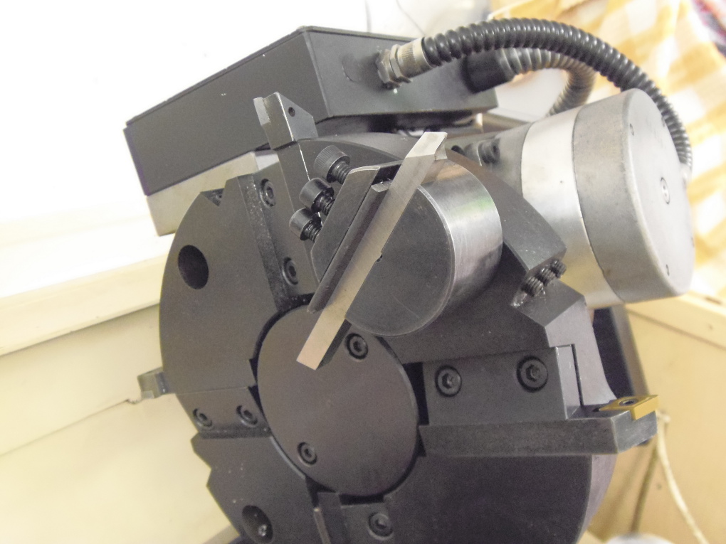
I have a toolholder which fits into one of the 20mm sockets and holds a threading tool upside down with the tip perfectly aligned to the workpiece centreline.
(I normally rub another tool edge across the end of the billet to scribe a centre and align to that)

I use M3 for conventional RH threads so that they are cut correctly, the tool being upside down is a real bonus because the swarf drops straight into the swarf tray
without any clogs you can get the other way up.
The tool is presented at 90 deg to the workpiece, so the cuts just need to be lighter than you might get away with if just cutting on one shoulder.

I have a 120 hole optical encoder with a hall effect switch triggered from a small rare earth magnet embedded in the drive pulley for an index.

This is a template I used for threading
Code:
;; Threading with G76 ;; Speed of 300 is stable and only requires F450 to cut 1.5mm thread ;; P[itch] ;; Z[FinalExtent] - Ensure there is an overrun element so that deceleration happens beyond end of thread, 3 mm sufficient in this example ;; I[ThreadPeakOffset - cant be 0, neg for external pos for internal, if diameter is critical you can add PeakOffset to Diameter to negate this value] ;; J[FirstCutDepth - positive offset] ;; R[DepthDegression 1.0 is constant depth 2.0 is constant area 1-2 depth decreases & area increases 2> area decreases] ;; K[FullThreadDepth positive offset beyond I for root of thread]- Q[CompoundSlideAngle eg 29.5] ;; H[SpringPasses at full thread depth] E[TaperAmount in units - normally 0] L[Taper- L0 None L1 entry L2 Exit L3 Both] #<_Diameter>=40 #<_Z_LeadIn>=15 #<_Pitch>=1.5 #<_Z_Finish>=-15 #<_PeakOffset>=-0.001 #<_First_Cut_Depth>=0.01 #<_Depth_Regression>=1.0 #<_ThreadDepth>=1.5 #<_CompoundSlideAngle>=0 #<_Spring_Passes>=2 #<_TaperAmount>=0 #<_TaperType>=0 #<_Feed>=1.5 #<_Speed>=300 G18 G21 G40 G49 G54 G80 G95 G90 G7 M101 P3 (SET PULLEY SETTING 3 FOR GOOD TORQUE) F#<_Feed> S#<_Speed> M3 G4 P10 M7 (GO TO OS DIA AND Z LEAD IN G0 X#<_Diameter> Z#<_Z_LeadIn> G76 P#<_Pitch> Z#<_Z_Finish> I#<_PeakOffset> J#<_First_Cut_Depth> R#<_Depth_Regression> K#<_ThreadDepth> Q#<_CompoundSlideAngle> H#<_Spring_Passes> L#<_TaperType> G00 X45 M9 M5 G28 M2

One thing I need to figure out is the lead in move


Not a problem now if you use my method.

I found the lead in was important for smooth threading ensuring an identical start point each time.
I settled upon having at least 15mm and the exact distance being a multiple of the thread pitch.
eg 1.5mm pitch / 15 mm lead in

regards
Last edit: 12 years 8 months ago by ArcEye.
The following user(s) said Thank You: Einar

Please Log in or Create an account to join the conversation.

More
12 years 8 months ago #44006 by ArcEye
Replied by ArcEye on topic Converting a Boxford 250B
A picture is worth a 1000 words......


Please Log in or Create an account to join the conversation.

More
12 years 8 months ago #44016 by Einar
Replied by Einar on topic Converting a Boxford 250B
I thought about that, but discarded it as it will drive the tool changer against the worm drive instead of the locking pawl.

But I did not think of your arrangement using the hole tool mounts. In that case if the cutting force is getting too high, the tool will be allowed to deflect by rotating in the hole rather than stripping the worm or wheel. Nice solution!

Alignment can be really simple and quick by making a gauge that have a height exactly the same as centerline above the cross slide. I have one for each of my manual lathes. I move this gauge against the cutting edge and when it is just about to catch the height is right. With an upside down tool it can be rotated until it rests on the gauge, then fixed.

I will probably also adopt your suggestion for cutoff tools. They really benefit from good swarf removal, and "overload protection".

Thanks for the template too. :cheer:

Please Log in or Create an account to join the conversation.

Time to create page: 0.067 seconds
Powered by Kunena Forum
