Converting a Boxford 250B
- Einar
- Offline
- Senior Member
-

- Posts: 47
- Thank you received: 1
I used ArcEye's tool changer .comp with some small tweaking.
Using the sensor did not work as I hoped. The debugging is not what I'm used to. I may get back to it later.
I made a new slotted wheel for the spindle with 90 slots. After several attempts with different opto sensors it finally works. The outputs from A and B are not optimal. At max RPM they are obviously at the edge of their bandwidth. The signal looks like shark teeth. Either I need to change the collector resistors, or maybe better: put an amplifier near the sensors. But it seems to work as it is. Using constant surface speed works all the way up.
It cut the pawn last week. I hope to wrap my head around thread cutting this weekend and make a test file for that. One thing I need to figure out is the lead in move. As the toolpost is back mounted it will need to cut away from the spindle. For a start I will probably make the thread at the largest diameter. It may also be a good time to optimize the accelerations.
Since it now can cut parts, I'm finally confident doing this conversion is going to be worth the many hours spent.
And a big thank you to all of you helping me through this forum, emails and IRC channel.

Now I need to document everything so I can debug it
Please Log in or Create an account to join the conversation.
- ArcEye
- Offline
- Junior Member
-

- Posts: 22
- Thank you received: 240
Glad you are making progress and the toolchanger worked for you.
It will work perfectly well without a sensor as previously described, but if you have it there, you want it to work, I know the feeling
")
As the toolpost is back mounted it will need to cut away from the spindle.
That is not necessary, this is what I do.
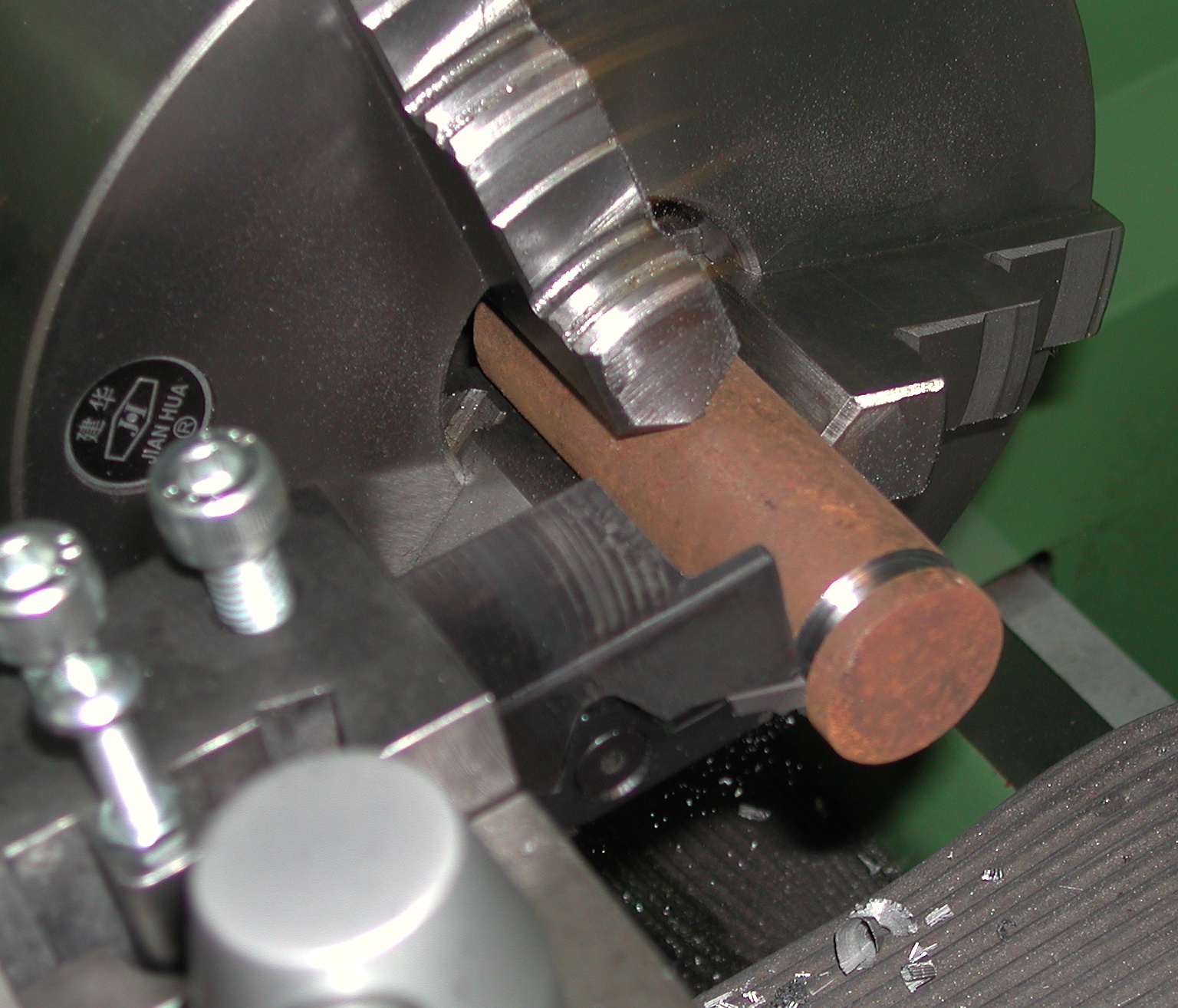
I have a toolholder which fits into one of the 20mm sockets and holds a threading tool upside down with the tip perfectly aligned to the workpiece centreline.
(I normally rub another tool edge across the end of the billet to scribe a centre and align to that)
I use M3 for conventional RH threads so that they are cut correctly, the tool being upside down is a real bonus because the swarf drops straight into the swarf tray
without any clogs you can get the other way up.
The tool is presented at 90 deg to the workpiece, so the cuts just need to be lighter than you might get away with if just cutting on one shoulder.
I have a 120 hole optical encoder with a hall effect switch triggered from a small rare earth magnet embedded in the drive pulley for an index.
This is a template I used for threading
;; Threading with G76

;; Speed of 300 is stable and only requires F450 to cut 1.5mm thread
;; P[itch]
;; Z[FinalExtent] - Ensure there is an overrun element so that deceleration happens beyond end of thread, 3 mm sufficient in this example
;; I[ThreadPeakOffset - cant be 0, neg for external pos for internal, if diameter is critical you can add PeakOffset to Diameter to negate this value]
;; J[FirstCutDepth - positive offset]
;; R[DepthDegression 1.0 is constant depth 2.0 is constant area 1-2 depth decreases & area increases 2> area decreases]
;; K[FullThreadDepth positive offset beyond I for root of thread]- Q[CompoundSlideAngle eg 29.5]
;; H[SpringPasses at full thread depth] E[TaperAmount in units - normally 0] L[Taper- L0 None L1 entry L2 Exit L3 Both]

#<_Diameter>=40
#<_Z_LeadIn>=15
#<_Pitch>=1.5
#<_Z_Finish>=-15
#<_PeakOffset>=-0.001
#<_First_Cut_Depth>=0.01
#<_Depth_Regression>=1.0
#<_ThreadDepth>=1.5
#<_CompoundSlideAngle>=0
#<_Spring_Passes>=2
#<_TaperAmount>=0
#<_TaperType>=0

#<_Feed>=1.5
#<_Speed>=300

G18 G21 G40 G49 G54 G80 G95
G90 G7
M101 P3 (SET PULLEY SETTING 3 FOR GOOD TORQUE)
F#<_Feed> S#<_Speed>
M3
G4 P10
M7
        (GO TO OS DIA AND Z LEAD IN
G0 X#<_Diameter> Z#<_Z_LeadIn>
G76 P#<_Pitch> Z#<_Z_Finish> I#<_PeakOffset> J#<_First_Cut_Depth> R#<_Depth_Regression> K#<_ThreadDepth> Q#<_CompoundSlideAngle> H#<_Spring_Passes> L#<_TaperType>
G00 X45

M9
M5

G28

M2
One thing I need to figure out is the lead in move
Not a problem now if you use my method.
I found the lead in was important for smooth threading ensuring an identical start point each time.
I settled upon having at least 15mm and the exact distance being a multiple of the thread pitch.
eg 1.5mm pitch / 15 mm lead in
regards
Please Log in or Create an account to join the conversation.
- ArcEye
- Offline
- Junior Member
-
- Posts: 22
- Thank you received: 240
Please Log in or Create an account to join the conversation.
- Einar
- Offline
- Senior Member
-
- Posts: 47
- Thank you received: 1
But I did not think of your arrangement using the hole tool mounts. In that case if the cutting force is getting too high, the tool will be allowed to deflect by rotating in the hole rather than stripping the worm or wheel. Nice solution!
Alignment can be really simple and quick by making a gauge that have a height exactly the same as centerline above the cross slide. I have one for each of my manual lathes. I move this gauge against the cutting edge and when it is just about to catch the height is right. With an upside down tool it can be rotated until it rests on the gauge, then fixed.
I will probably also adopt your suggestion for cutoff tools. They really benefit from good swarf removal, and "overload protection".
Thanks for the template too.
Please Log in or Create an account to join the conversation.
- ArcEye
- Offline
- Junior Member
-
- Posts: 22
- Thank you received: 240
I will probably also adopt your suggestion for cutoff tools. They really benefit from good swarf removal, and "overload protection".
Exactly right.
I use the same principle on my big manual lathe and run the motor backwards to part off
regards
Please Log in or Create an account to join the conversation.
- Einar
- Offline
- Senior Member
-
- Posts: 47
- Thank you received: 1
I have now tried some thread turning, and therein also some challenges.
The toolchanger is behind the spindle, so turning an outside thread it is done away from the chuck.
Often there will be a shoulder that prevents much of an entry move. So it becomes important that the thread pitch is correct as soon as possible.
It is not!
The first picture shows a thread done at 300RPM with 2.5mm pitch. The first revolution have a pitch close to 5mm. Then blending
into the correct pitch.
My first thought was that the PID overshoots. But no, then it would also have a section with too fine pitch as it swings into the correct feed.
I think it is something else. Come with me out of the workshop and go for at drive in the car. We'll take the fast one.
On our way we will have to enter a highway. When entering the entry ramp I start looking in the mirror for a suitable opening in the traffic. I target the last car before the opening and start accelerating so I will be at equal speed at the same time as it have passed me with a suitable safety distance. (I'm not a bumper rider.) This method I have found to be relaxed and withouth any large corrective actions.
I have sometimes seen another strategy: A driver stops in the entry ramp waiting for an opening. Then just after the last car passed him he take off with smoking tires and shoots onto the highway far behind the last car. Then he will drive at a much faster speed than the rest to catch up with traffic, and slow down again as he does. That's where his strategy stands out as not very smooth!
I now think that LinuxCNC is using the last strategy. Before trying it out I thought it would predict when the index mark would pass the next time and start accelerating before that. Much like the code in a petrol engine ECU that will time the preignition to a specific number of degrees before TDC by counting pulses from the previous index mark.
Well, long story, but can someone tell me if I'm right or wrong?
If the strategy is to catch up what is lost in acceleration I will have to cut against the chuck end, as there is little or no problem at the end of the cut. It will just retract and "slam the brake". But it's out of cut, so lost synch is not a worry.
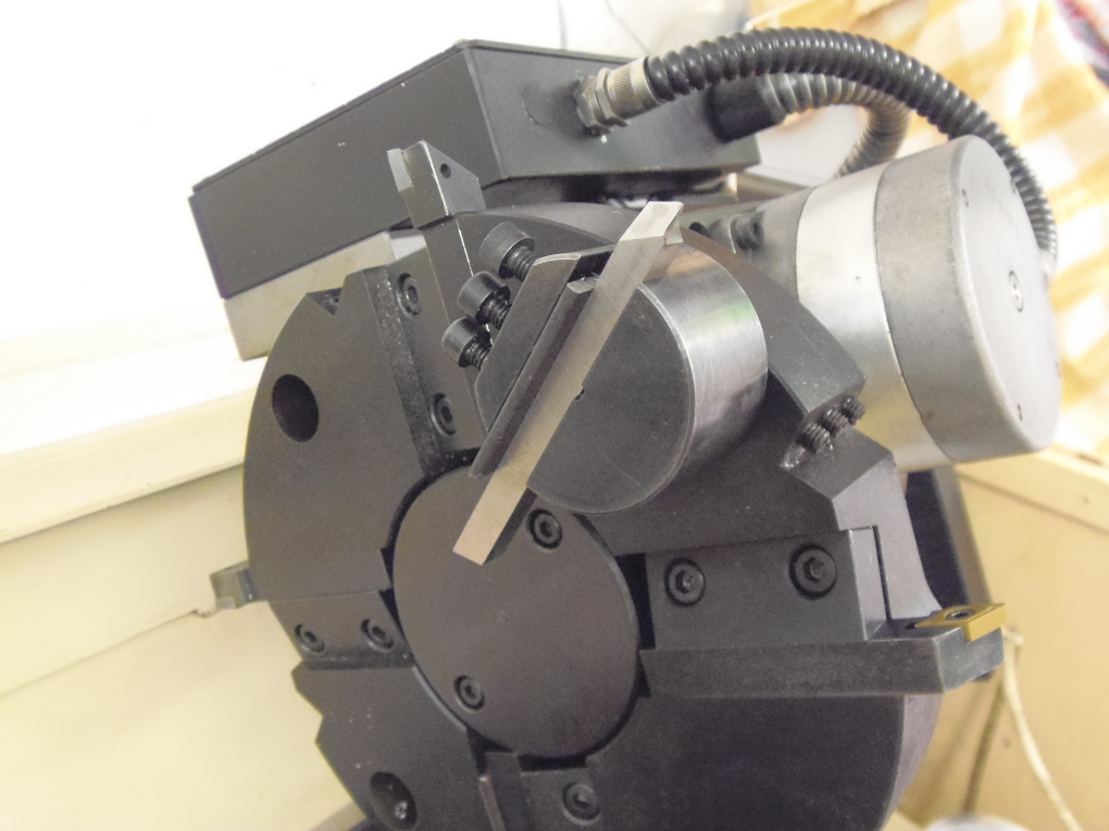
1. I can mount a toolpost in front of the spindle to carry screwcutting tools.
2. I can mount the tool upside down.
3. On the IRC I got an out of the box tip: Make a toolholder that hooks under the workpiece and ends up in front of it.
4. Also from the IRC: Use a Die in one of the circular holes in the toolchanger.
They have some warts though:
1. In my attempts to make the problem as small as I can, I started tuning speeds and accelerations. A lot could be gained in Z (which is what affects this problem the most). But in X the weight of the slanted slide really show one of the disadvantages of a slant bed. In -X it can accelerate fine, and to a high speed. But in +X it have to lift the slide, heavy toolchanger and the motor itself. So the speed and accel needs to be kept very low. Mounting another toolholder will not help!
2. The cutting force will not be against the locking pawl of the toolchanger.
3. If made for anything but small diameter workpieces it will hit the bed.
4. The cutting forces will be high. And my spindle motor have fixed gearing, so is very weak at low speeds. The original was from 200-3500RPM.
Hopefully someone can extend my list of options.
I'm not sure if I wrote this before, but my encoder (Picture 2) has 90 shallow slots for the A and B reading forks and one deeper slot for the index. The index reading fork hangs off the side of the block that carry A and B. That's just because the only reading fork I found that work a deep slot is physically different from the other two.
UPDATE:
I was using G76 threading. So I obviously left out a piece of important information. Sorry about that.
Now I just tried out G33. And the problem does not seem to apply to G33 !?!
Before, I started out at Z-15 and X 1mm outside the thread peak (also tried other offsets). 300RPM.
Issued code g76 P2.5 z3 i-1 j0.3 k2.5 r2.0 q-30 e0.5 l1re.
Now I blacked the surface with a sharpie, moved to Z-15, plunged the tool to a depth of 0.1mm and issued G33 Z0 K2.5
And the result looks just fine! There probably still is an error due to acceleration, I just can't see it since it is so short.
Checking the user manual the Technical Info says G33 does it just like I hoped it did. Rechecking the manual for G76 it just refers to Technical Info for G33, saying it is based on G33.
So either there is a bug in the implementation of G76, or I am not using it correctly. Can anyone please look at my G76 code?
I know the Q is probably wrong, but what is right when cutting towards higher Z?
So for now it seems I can do what I want. I just have to use a G33 loop building routine to make up the needed passes. I have seen one around here.
Please Log in or Create an account to join the conversation.
- BigJohnT
-

- Offline
- Administrator
-

- Posts: 3990
- Thank you received: 994
My CHNC Z axis is:
MAX_VELOCITY = 6.0
MAX_ACCELERATION = 35
FERROR = 0.025
MIN_FERROR = 0.005
Which is still on the low side of acceleration.
Have you tuned your axes with Halscope to get the best performance and least following error?
JT
Please Log in or Create an account to join the conversation.
- ArcEye
- Offline
- Junior Member
-
- Posts: 22
- Thank you received: 240
The toolchanger is behind the spindle, so turning an outside thread it is done away from the chuck.
Often there will be a shoulder that prevents much of an entry move. So it becomes important that the thread pitch is correct as soon as possible.
It is not!
The lead in is crucial in my experience, for matching feed to exact spindle speed to get the right pitch.
That is why I use a reversed cutting tool and cut from the front.
The other option is via a gang tooling screw plate I made and fitted to the X axis below the ATC
This would allow cutting from in front of the workpice, ie conventional screw cutting in M3, but I found the reversed tool works fine.
But in X the weight of the slanted slide really show one of the disadvantages of a slant bed. In -X it can accelerate fine, and to a high speed. But in +X it have to lift the slide, heavy toolchanger and the motor itself. So the speed and accel needs to be kept very low. Mounting another toolholder will not help!
The movements of the X axis after going to the initial position are so small, I can't see it being any problem.
The place where there can be problems if any, is the lift and retraction at the end of the cut, returning to start position again.
If your settings are near the edge, that is where you might lose steps.
I did have some problems initially, until I replaced a 24v PSU with a 76V one and the drivers with 8A Leadshine ones
My MAX_VELOCITY is about 25 - 30 and MAX_ACCELERATION is something like 120.
An area I would look at is the spindle.
I have a DC motor and pulleys, which gives lots of torque at the lowest speed settings.
I generally thread at 300 - 450 rpm
It looks as though you have a VFD and 3 phase motor with no pulley gearing.
Although there are sometimes settings to boost torque, I found previously that at low speed, torque was lacking using a lathe with that set up.
If the spindle slows and the acceleration is set low, the Z axis may not be able to compensate in time and that will produce a overly wide pitch too.
You might have to thread at a higher speed where the torque is better, but that will make lead in crucial.
I use a 120 hole optical encoder plate, which gave significant performance benefits over a previous 60 hole one
I would have thought 1 pulse per 4 degrees (90 hole) should be adequate.
I haven't looked at it in detail, but as far as I am aware, G76 is just a canned cycle using G33, so there should not be any significant differences.
regards
Please Log in or Create an account to join the conversation.
- andypugh
-

- Offline
- Moderator
-

- Posts: 19875
- Thank you received: 4642
The toolchanger is behind the spindle, so turning an outside thread it is done away from the chuck.
Can you use a left-handed thread?
Please Log in or Create an account to join the conversation.
- Einar
- Offline
- Senior Member
-
- Posts: 47
- Thank you received: 1
Increasing the voltage is not an option. It is around 80V. The only drive I have that better this is a 10A 170V, but I have other plans for it.
I will live with low X speed. Much for the reason you wrote ArcEye.
The spindle motor is geared down a bit. At 3000RPM it runs at 175Hz! And it's a 1480RPM motor. So it is around 52:30.
The motor is 2.9Hp and this is not a big machine. It obviously was capable of threadcutting before the conversion.
I have improved Z a lot both in speed and acceleration, but if anything it made the problem worse in G76. ????
JT: If your numbers are in inches, mine is not as good.
And I did use halscope, but does not really understand other than if there is improvement or not. The number is very low, but I don't know what units. If it is mm then it looks fine. I don't remember the number. I updated the univstep.ini here: sjaavik.no/linuxcnc-dev/univstep/
I did try a G33 loop and it looked nice and synchronized. I will have to do some serious tests and see how my thread gauge agrees.
I can use a left handed thread. But not often. And I have no LH thread gauges, so I cannot check the result properly.
Please Log in or Create an account to join the conversation.