Emco Compact 5 PC auto tool changer
- krlynn
- Offline
- Senior Member
-

- Posts: 40
- Thank you received: 0
I found a YouTube video of one setup to run on Mach 3 and another fitted with a handle for manual operation , but so far none configured for control by linuxCNC.
Also found this :
"To be honest I can't see any advantage to using a stepper. The original
Emco changer was open loop. They simply switched the motor on for a
fixed time to change one tool the reversed to lock it. This was then
repeated as many times as needed to select the desired tool. It was
pretty slow and occasionally missed if the mechanism was a bit stiff. I
rebuilt one one with a faster motor and a switch to signal that the pawl
had engaged. The switch allows the motor to be run continuously until
the correct tool is selected. Worst case tool change time was about 1.5
secs (say tool 4 to tool 3), best case less than 0.5 sec (from say tool
2 to tool 3). I also built one from scratch using the same system. Both
are very reliable."
This : www.scribd.com/doc/74000903/Compact5-Cnc...-Changer-Mach3-Macro
And this : www.machsupport.com/forum/index.php?acti...rintpage;topic=970.0
Please Log in or Create an account to join the conversation.
- ArcEye
- Offline
- Junior Member
-

- Posts: 22
- Thank you received: 240
Look in
wiki.linuxcnc.org/cgi-bin/wiki.pl?ContributedComponents
I have written 2 for that sort of ATC and a third was written on a slight variation of one of mine by another user
Either the 4 sensor version which was adapted from my Orac changer component
wiki.linuxcnc.org/cgi-bin/wiki.pl?Contri...oolchanger_component
or the oracchanger component itself
wiki.linuxcnc.org/cgi-bin/wiki.pl?Contri...oolchanger_component
should be quite close
The Boxford toolchanger also uses a similar past the pawl and reverse but without any sensors
wiki.linuxcnc.org/cgi-bin/wiki.pl?Contri...oolchanger_component
It just depends exactly how the tool positions are determined and whether it moves backwards and forwards just using a stepper, or if it has a motor which can be switched from forward to reverse.
I think the Orac and Emco 120 had motors (off the top of my head) and the Boxfords uses steppers, but Nema 23 or 34 on the bigger ones, not 17.
I wouldn't bother about toolchange timing 'pissing contests', what you want is one that works, not spend a load of money to shave a second off the toolchange.
regards
Please Log in or Create an account to join the conversation.
- krlynn
- Offline
- Senior Member
-
- Posts: 40
- Thank you received: 0
Completely agree the objective is just to get it to work reliably.
Look in
wiki.linuxcnc.org/cgi-bin/wiki.pl?ContributedComponents
I have written 2 for that sort of ATC and a third was written on a slight variation of one of mine by another user
Either the 4 sensor version which was adapted from my Orac changer component
wiki.linuxcnc.org/cgi-bin/wiki.pl?Contri...oolchanger_component
or the oracchanger component itself
wiki.linuxcnc.org/cgi-bin/wiki.pl?Contri...oolchanger_component
should be quite close
The Boxford toolchanger also uses a similar past the pawl and reverse but without any sensors
wiki.linuxcnc.org/cgi-bin/wiki.pl?Contri...oolchanger_component
It just depends exactly how the tool positions are determined and whether it moves backwards and forwards just using a stepper, or if it has a motor which can be switched from forward to reverse.
I think the Orac and Emco 120 had motors (off the top of my head) and the Boxfords uses steppers, but Nema 23 or 34 on the bigger ones, not 17.
I wouldn't bother about toolchange timing 'pissing contests', what you want is one that works, not spend a load of money to shave a second off the toolchange.
Please Log in or Create an account to join the conversation.
- ArcEye
- Offline
- Junior Member
-
- Posts: 22
- Thank you received: 240
Thanks, although I'm at a stage where just about everything goes over my head. I jumped on the tool changer because it doesn't seem like they turn up very often.
Probably a good move, don't have to fit it the next day.
No matter how you get it working, you need to find out how it works first.
There will be info on the net, if you are lucky you may even find a manual.
As an interim measure, if it is stepper powered, it is quite simple to define it as a rotary axis and just jog it manually.
regards
Please Log in or Create an account to join the conversation.
- tenaja
- Offline
- Junior Member
-
- Posts: 21
- Thank you received: 3
I have seen some photos of broken pawls; replacing it with something thicker seems reasonable.
Please Log in or Create an account to join the conversation.
- ArcEye
- Offline
- Junior Member
-
- Posts: 22
- Thank you received: 240
I have not converted my Compact 5 CNC's to LCNC yet. However, if your tool changer is the same as the ones on mine (in photos I've seen they look the same), then the motor is NOT a nema 17 stepper. As described in your OP, they are typically just a DC gear motor; it is driven one way for a specific time (to pass the pawl), then driven the other way to stall on the pawl
In which case it is the same as the Orac and the 120, one of those two changer components should work without much alteration
regards
Please Log in or Create an account to join the conversation.
- tenaja
- Offline
- Junior Member
-
- Posts: 21
- Thank you received: 3
A guy could get creative and put a current sensor on the motor. It will not tell you when the cog passes the pawl, but it will tell you when the toolchange motor is stalled--meaning the change is done and locked. So many fun things to do...so little time.
Please Log in or Create an account to join the conversation.
- ArcEye
- Offline
- Junior Member
-
- Posts: 22
- Thank you received: 240
the Compact 5 is without sensors.
I doubt it, a firm like Emco does not make something with no way to tell what tool is selected.
There are 2 possible types of sensors.
There are greyscale sensors reading a disc inside the ATC, from which a truth table can determine which quadrant is currently over the sensors
The Orac had 3 sensors reading the disc, the Emco 120, which I think had more tools, had 4 sensors
There are proximity or similar sensors, normally operating on a void in the casting. These tend to be used to mark out the No1 tool position, albeit some have
each tool station marked and a seperate sensor for No1.
The Boxford could get away without any sensors because it had a stepper driven ATC
That meant it was possible to calculate the steps required to move between tools, which just required the operator to input which tool was current and
immediately the component could change to any tool commanded.
Being driven by a DC motor offers no such positional feedback - thus there must be sensors
regards
Please Log in or Create an account to join the conversation.
- krlynn
- Offline
- Senior Member
-
- Posts: 40
- Thank you received: 0
As an interim measure, if it is stepper powered, it is quite simple to define it as a rotary axis and just jog it manually.
I have not converted my Compact 5 CNC's to LCNC yet. However, if your tool changer is the same as the ones on mine (in photos I've seen they look the same), then the motor is NOT a nema 17 stepper. As described in your OP, they are typically just a DC gear motor; it is driven one way for a specific time (to pass the pawl), then driven the other way to stall on the pawl. Not likely to be a difficult routine to write, but not as easy as turning a stepper. I'm not trying to discourage you, and maybe your TC has been retrofitted, but I just want you to be aware.
No stepper is mounted on this ATC. My OP was probably confusing. I bought the ATC along with a separate Nema 17 stepper that the eBay Seller had intended to mount and control with Mach 3, but he never got around to it. The ATC was still new in its original Styrofoam enclosure.
Again, I jumped on this ATC because I thought it might be a long time before I got another shot at one in mint condition. But I don't have any business trying to sort how to make it work on my own right now. I have a lot of basics to master first. Just couldn't help but wonder if anyone else had one running with linuxcnc. I also asked in the Yahoo Emco group. No replies so far. I found several threads in which the Emco Compact 5 ATC was discussed, but I've yet to run across a photo of (or even a reference to) an unmodified EMCO C5 PC with a stock ATC mounted.
What I've gathered about how the Emco C5 ATC was designed to work is included below. I'll share it for the sake of anyone else here who might be interested.
The conclusion I took from this thread in the machsupport.com forum is that the C5 tool-changer lacks sensors and “is very open loop.”
The forward rotation is timed by a resistor capacitor circuit. The value of the two components determines the time of the forward motion. Then the circuit reverses against the stop at a reduced voltage which is constant. (Posted by Jeff K at groups.yahoo.com/neo/groups/Emco_cnc_use...ations/messages/4539 )
One of the power supply outputs is 10 Volts. This is an unregulated voltage but it is smoothed by 3x10.000 uF capacitors. This output is used to drive the stepper motors.
In forward motion the turret motor is connected directly to this 10V output. There is no difference in the open voltage or with running motor because of the high power of this output. Five diodes (1N4007) in series are connected parallel to the motor with cathode to the plus and anode to the minus side. This has no effect in forward motion.
In reverse mode however three parallel resistors (100 Ohm, 4 Watt which gives 33 Ohm) are connected in series with the motor. Now the diodes conduct so over the motor will be 5x0.7=3.5 Volt. The internal resistance of the motor determines the current that will flow with this voltage. The motor can take this without getting hot over time.
BTW in my machine the 10 Volts output actually gives 13.5 Volts. This means that over the resistors remains 13.5-3.5=1o Volts. With 33 Ohm this gives 10/33=0.303 Ampere. So the motor reverse current is 303 mA. (Posted by Henk at groups.yahoo.com/neo/groups/Emco_cnc_use...ations/messages/3161)
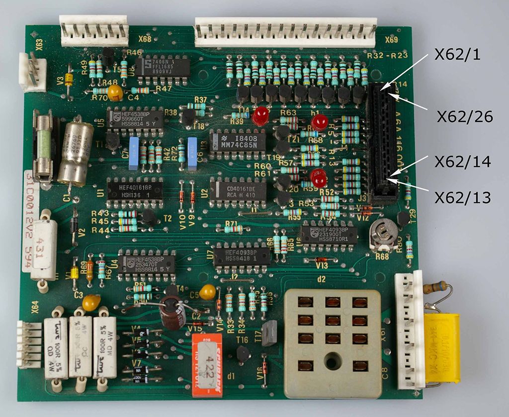
The DNC board has 5 different connectors. X62 is the one for external connections.
When you send a low pulse to pin2, the turret starts rotating until it overruns the next position. Then the DNC board will reverse the turret motor with reduced current. It will keep doing this even after the hitting the lock. That way the turret will be held to the lock with some torque. The length of the pulse is not important. (Posted by Henk at groups.yahoo.com/neo/groups/Emco_cnc_use...ations/messages/2048 )
C2 is the timing capacitor for the forward movement and it works together with R67 and R68. The other one, C1 is a power supply capacitor.
If the range of the potentiometer R68 is insufficient, you could either replace C2 for a new one or replace R67 by a resistor different value.
If you want to speed up the process, you could do some tuning to the DNC board. In most cases, the turret loses time because it overruns the lock position too much, then returns to the lock position and wait there a while before starting to turn again.
So, the optimum speed for the standard turret is to stop moving forward right after passing a lock position. Then turn backwards until it hits the lock position and stay there for only a short moment before starting in forward direction again. The turning speed of the turret will remain as slow as before, but the overall speed will be improved.
To set the timing for optimum performance you should know that only the forward pulse is variable (to be set with potentiometer R68). So you should make the reverse pulse variable also. You can do this by replacing resistor R69 with a resistor and a potentiometer. Now you can set reverse timing with this new potentiometer. When adjusting reverse time make sure that the turret hits the lock position every pass when turning backwards. Otherwise it could get out of sync after a few passes.
The value for the new resistor and potentiometer depends a little on the value that Emco used in your board and the condition of the old capacitors. The length of the reverse pulse can be calculated by (R69*C3)/1000.
If on your board R69 and C3 are 330K and 10 microF the reverse pulse will be 3.3 seconds, which is very safe but also slows down the process.
If you replace R69 with a 150K resistor and a 0 to 100K potentiometer you can set the reverse pulse from anything between 1.5 and 2.5 seconds.
The forward pulse is determined by R67, R68 and C2. The length of the pulse is ((R67+R68)*C2)/1000.
Emco used different values in different DNC boards. When on your DNC board R67 resistor is 22K and R68 potentiometer is 0 to 10K and C2 capacitor is 100 microF you can set the forward pulse from 2.2 to 3.2 seconds. If necessary you can replace R67 with a different value to shift these limits.
Remember that the turning speed of the turret is not always the same, depending on temperature and other circumstances. This will cause problems if you set timing too critical. (Posted by Henk at www.machsupport.com/forum/index.php/topi...ations/messages/1633)
I found a fairly high resolution scan of the wiring diagram for a C5 CNC. It was uploaded in three parts, which I stitched back together in Photoshop, making a 5.24 MB jpg, which converted to a 4.75 MB pdf file. I’d be pleased to put those up here, but given the size thought I should probably ask first.
I have seen some photos of broken pawls; replacing it with something thicker seems reasonable.
Me too, but my first thought was to wonder whether the original design reflected some purpose (e.g., to act as a fail-safe mechanism).
Below is a photo of the EC5 CNC DNC board.
Please Log in or Create an account to join the conversation.
- ArcEye
- Offline
- Junior Member
-
- Posts: 22
- Thank you received: 240
Well to cut right through.
It is normally powered by a DC motor (which you don't have) and an extremely inventive system which uses the motor and a board (which you don't have).
You have a stepper motor and hopefully a plan to attach it, thereafter you are back with the Boxford scenario, which is equally workable
When you get it turning, come on back
regards
Please Log in or Create an account to join the conversation.