- Hardware & Machines
- CNC Machines
- Turning
- Please help me with my ground wiring for my sherline lathe - running into issues
Please help me with my ground wiring for my sherline lathe - running into issues
- ffffrf
- Offline
- Senior Member
-

Less
More
- Posts: 51
- Thank you received: 2
15 Jul 2024 22:29 #305286
by ffffrf
Please help me with my ground wiring for my sherline lathe - running into issues was created by ffffrf
Hey everyone, I am having an issue where isolated analog output is failing to control my sherline spindle. This issue started after I added a spindle encoder. However, there are other issues going on that make me think there is a serious issue in my ground circuitry. I did a crappy job and there are probably lots of ground loops. Despite removing the encoder, I still get spindle control issues. As it stands, both axis work fine. At one point prior to encoder, everything worked fine.
What makes me suspect a (Dangerous) ground issue - is that moving around my isolated DC power brick (Which hooks into spin- and spin+ to get me my 0-10v range) can sometimes cause the spindle to turn on.
Currently, both axis work fine.
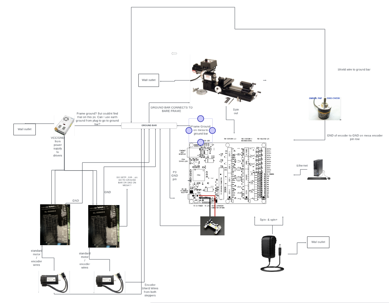
Therefore, I am planning on redoing my wiring, particularly when it comes to ground circuitry. I made a diagram of the new proposed ground circuit and wanted to see if anyone could verify this should work correctly.
My biggest question for this is: Does step- and dir- connect to GND on the steppergen of my 7i96s, or to the ground bar that connects to the sherline frame?
Attachments:
Please Log in or Create an account to join the conversation.
- tommylight
-

- Away
- Moderator
-

Less
More
- Posts: 21143
- Thank you received: 7221
25 Jul 2024 01:01 #305985
by tommylight
Replied by tommylight on topic Please help me with my ground wiring for my sherline lathe - running into issues
Thank you for your patience, have not seen this in time.
Both drawings are wrong, but not your fault as the whole internet refers to 0V as gnd, and that is wrong for the last 30 or more years. Skipping that...
In short, ground from mains to ground bar, from ground bar to power supply, another one from bar to motor frame or motor ground wire, encoder shield to ground bar. No more.
If you have betetr quality drives, use only two wires for step and two for dir, wire step+ to step/pulse+ and step- to step/pulse-, same for dir pins.
Please Log in or Create an account to join the conversation.
Moderators: piasdom
- Hardware & Machines
- CNC Machines
- Turning
- Please help me with my ground wiring for my sherline lathe - running into issues
Time to create page: 0.102 seconds

