7i47s documentation verbage (analog i/o)
- jCandlish
-
 Topic Author
- Offline
- Premium Member
-

- Posts: 151
- Thank you received: 4
Specifically the documentation says:
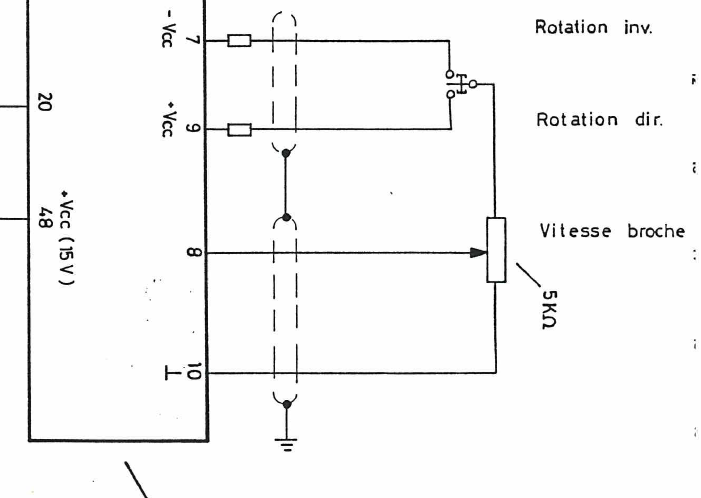
ANALOG OUT
The 7I47S provides one analog output for spindle control. The analog output is a
isolated potentiometer replacement type device. It functions like a potentiometer with
ANALOG + being one end of the potentiometer, ANALOG OUT being the wiper and
ANALOG- being the other end. The voltage on ANALOG out can be set to any voltage
between ANALOG- and ANALOG+. Polarity and voltage range must always be observed
for proper operation. The voltage supplied between ANALOG+ and ANALOG- must be
between 5VDC an 15VDC with ANALOG + always being more positive than ANALOG-.
The analog output voltage is set by PWM from the controller. The optimum PWM
frequency is approximately 5KHz, Higher frequencies will have lower ripple but more nonlinearity,
lower frequencies will have better linearity but more ripple.
Is that meant to read that the absoulte value of the ANALOG- and ANALOG+ reference voltages must be between 5 and 15 volts???
Specifically is ANALOG- == -10VDC && ANALOG+ == +10VDC OK ???
but ANALOG- == -4 VDC && ANALOG+ == +12VDC NOK because ANALOG- is not negative enough ???
or ANALOG- == +3 VDC && ANALOG+ == +10 VDC is NOK because ANALOG- is not positive enough???
Also, if the circuit is isolated, to what ground source are the ANALOG[+-] signals referenced???
Sorry, this part of the documentation is not clear to me.
Can the 7i47s wiper provide deltaV =30V , ie +-15VDC range???
Page 10 of the 7i47s manual v1.1 is missing the spec for line-item (ANALOG+ - ANALOG-)
Thanks
_jC
.
Please Log in or Create an account to join the conversation.
- PCW
-

- Away
- Moderator
-

- Posts: 18818
- Thank you received: 5196
So if you want bipolar output (not recommended) maximum range would be -7.5 to +7.5V to stay within the 15V maximum rating
The output is totally isolated from the PC
The only "ground" is the ends of the "potentiometer"
(just like a potentiometer). For the intended unipolar
operation, ANALOG- would connect to the VFDs ground pin,
ANALOG+ to +10V, and ANALOGOUT to the VFDs input
Please Log in or Create an account to join the conversation.
- jCandlish
-
Topic Author
- Offline
- Premium Member
-
- Posts: 151
- Thank you received: 4
So max wiper deltaV == 15v.
Not so good for the Lenze 490 DC speed controller
 Its potentiometer rails are at +-15VDC.
Maybe the Lenze has a trimpot?
Otherwise looks like something I need to add to a helper circuit board...
Please Log in or Create an account to join the conversation.
- PCW
-
- Away
- Moderator
-
- Posts: 18818
- Thank you received: 5196
Please Log in or Create an account to join the conversation.
- jCandlish
-
Topic Author
- Offline
- Premium Member
-
- Posts: 151
- Thank you received: 4
You could also do it with a floating 15V power supply and ground either the +15 or -15 end of the PS with the OPTOs or a relay
Yeah, I just trying to puzzle that out. Not an EE.
Looks like I need switch both legs of the wiper pot (Vcc+ > Vcc- ), but how???
This has to be an idiom.
Please Log in or Create an account to join the conversation.
- PCW
-
- Away
- Moderator
-
- Posts: 18818
- Thank you received: 5196
But there are a lot of funny side effects (full speed backwards when disabled is one)
With a floating 15V supply you use a double pole double throw switch or relay to reverse the output (always the ANALOG- and ANALOG out)
this is a standard reversing switch but will only work with a floating supply
Please Log in or Create an account to join the conversation.
- jCandlish
-
Topic Author
- Offline
- Premium Member
-
- Posts: 151
- Thank you received: 4
... lot of funny side effects (full speed backwards when disabled is one)
With a floating 15V supply you use a double pole double throw switch or relay to reverse the output (always the ANALOG- and ANALOG out)
this is a standard reversing switch but will only work with a floating supply
I'm too stupid to figure this out. In the floating circuit, where do I put the other half of the dpdt switch to reverse the sense of the wiper control at the zero-crossing???

thx
_jC
Please Log in or Create an account to join the conversation.
- jCandlish
-
Topic Author
- Offline
- Premium Member
-
- Posts: 151
- Thank you received: 4
PCW wrote:
... lot of funny side effects (full speed backwards when disabled is one)
With a floating 15V supply you use a double pole double throw switch or relay to reverse the output (always the ANALOG- and ANALOG out)
this is a standard reversing switch but will only work with a floating supply
I'm too stupid to figure this out. In the floating circuit, where do I put the other half of the dpdt switch to reverse the sense of the wiper control at the zero-crossing???
thx
_jC
The best solution I can find is a using triple-pole switch. I suppose there is a simular solution for the non-floating case. Can't for the life of me see a double pole switch solution.

Rgds
_jC
.
Please Log in or Create an account to join the conversation.
- PCW
-
- Away
- Moderator
-
- Posts: 18818
- Thank you received: 5196
- jCandlish
-
Topic Author
- Offline
- Premium Member
-
- Posts: 151
- Thank you received: 4
ikm.digitrax.com/questions/93/DPDT+-+Dou...ow+Electrical+Switch
Thanks, but ...
where do I put the other half of the dpdt switch to reverse the sense of the wiper control at the zero-crossing???
Still too stupid to see it. I will reflect upon this.
Need to see what is in the comat relays, and if they can be wired in this way
Please Log in or Create an account to join the conversation.