Brushed closed loop using encoders and h-bridge
- tschraeder
- Offline
- New Member
-

- Posts: 4
- Thank you received: 0
I've already done a 3-axis stepper setup with LinuxCNC a while back and that was fun, but now I want to move to a closed loop servo setup. At this point it is more proof of concept and for my own learning, so I don't want to sink a ton of money into it (yet... we know how this goes). I've been reading everything I can find on closed loop servo setups with LinuxCNC and also the PDF manuals, but need some guidance to fill in the elusive portions.
What I want is a 3-axis, closed loop, brushed DC servo setup using quadrature rotary encoders. I want to close the position loop on the LinuxCNC side, not on the servo drive side.
I've read through the wiki.linuxcnc.org/cgi-bin/wiki.pl?LinuxCNC_Supported_Hardware page a whole bunch of times and saw the Pluto-P board but am hesitant to go that route. I would rather go with a Mesa or Pico board since they seem more reliable and also allow future expansion.
The brushed dc motors that I already have are relatively low power (about 100W) so first I would like to use a simple H-bridge to drive them with PWM and direction signals. Is this method possible to run closed loop on the LinuxCNC side with the correct interface hardware? Say a Mesa 5i25 with the correct daughter card?
Thanks for the help and suggestions are welcome!
-Travis
Please Log in or Create an account to join the conversation.
- andypugh
-

- Offline
- Moderator
-

- Posts: 23527
- Thank you received: 5005
The brushed dc motors that I already have are relatively low power (about 100W) so first I would like to use a simple H-bridge to drive them with PWM and direction signals. Is this method possible to run closed loop on the LinuxCNC side with the correct interface hardware? Say a Mesa 5i25 with the correct daughter card?
All things are possible. You can even (just) do closed-loop servo control with the parport:
emergent.unpythonic.net/projects/01142347802
This exists in the LinuxCNC sample configs as etch-servo.
If you want to use a mesa 5i25 then you would be looking at 5i25 + 7i85S (the daughter-board might not actually be necessary). You need to make sure that you get a firmware with PWM outputs, most of the 5i25 daughter boards use DACs to produce analogue output for servo drives.
I am less familiar with the Pico setups but pico-systems.com/univpwm.html looks likely.
Please Log in or Create an account to join the conversation.
- jmelson
- Offline
- Moderator
-
- Posts: 827
- Thank you received: 160
Yes, the Pico Systems PWM controller will control up to 4 axes, and our PWM servoI am less familiar with the Pico setups but pico-systems.com/univpwm.html looks likely.
amps will drive the motors. You can use one of these servo amps to run a spindle,
too. I have done this on my minimill, and use it for rigid tapping. (The stock
motor speed control does only one direction.) I use it open-loop even though
I have an encoder on the spindle, but others have added a little HAL code to
read the encoder and adjust spindle speed in a closed-loop manner.
Jon
Please Log in or Create an account to join the conversation.
- tschraeder
- Offline
- New Member
-
- Posts: 4
- Thank you received: 0
- LinuxCNC > dumb interface > dumb servo drives > motors > encoders > dumb interface > LinuxCNC
- LinuxCNC > smart interface > dumb servo drives > motors > encoders > smart interface > LinuxCNC
- LinuxCNC > smart interface > smart servo drives > motors > encoders > smart interface > LinuxCNC
- a dumb interface card is basically the etch_servo example that communicates via the parallel port and is opto-isolated
- a smart interface card communicates via PCI or the parallel port and performs tasks such as opto-isolation and encoder counting
- a dumb servo drive takes an input voltage and amplifies it with no feedback, so the assumption is that motor velocity is proportional to the control voltage (generic H-bridge).
- a smart servo drive includes some feedback control of the voltage and/or current applied to the motor (or even position). This is referred to as torque or velocity motor control.
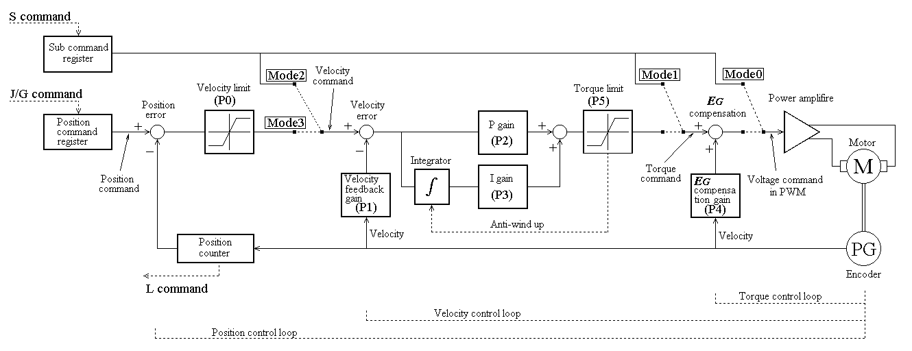
The Elm controller previously mentioned has a nice block diagram showing these different modes of operation possible (see figure below). Mode 0 would refer to my reference of a "dumb" servo drive. How important is it that the servo drive have torque or velocity control?
From what I've gathered, it seems important to have some external hardware that handles PWM generation and encoder counting, since directly relying on LinuxCNC for this via the parallel port is limited in performance. Is this correct?
Lastly, I've been searching a lot about closed loop servo control using LinuxCNC and have yet to find a single source that addresses these types of questions. Does a single source exist? I understand there are many ways to accomplish CL servo control, but I'm surprised there isn't a wiki page that outlines it since there seems to be a high learning curve.
-Travis
Please Log in or Create an account to join the conversation.
- jmelson
- Offline
- Moderator
-
- Posts: 827
- Thank you received: 160
The Pico Systems PWM controller not only has a hardware encoder counter, it also has
From what I've gathered, it seems important to have some external hardware that handles PWM generation and encoder counting, since directly relying on LinuxCNC for this via the parallel port is limited in performance. Is this correct?
hardware PWM generators. generating PWM with software is pretty much impossible
at higher PWM frequencies. Our PWM generator runs at 40 MHz, giving 25 ns timing
resolution of the pulse width. This allows 800 steps of pulse width (1/8 of a %) at
50 KHz.
Well, there may be such a description. But, at the top of this section, there areLastly, I've been searching a lot about closed loop servo control using LinuxCNC and have yet to find a single source that addresses these types of questions. Does a single source exist? I understand there are many ways to accomplish CL servo control, but I'm surprised there isn't a wiki page that outlines it since there seems to be a high learning curve.
-Travis
pinned documents about Pico and Mesa products. You might read the one
from Pico about the PWM system. (There is also a description of our stepper
controller and analog servo interface.)
Jon
Please Log in or Create an account to join the conversation.
- tschraeder
- Offline
- New Member
-
- Posts: 4
- Thank you received: 0
The Pico Systems PWM controller not only has a hardware encoder counter, it also has
hardware PWM generators. generating PWM with software is pretty much impossible
at higher PWM frequencies. Our PWM generator runs at 40 MHz, giving 25 ns timing
resolution of the pulse width. This allows 800 steps of pulse width (1/8 of a %) at
50 KHz.
When you have hardware that counts the encoders, what type signal is sent back to LinuxCNC? Is it the number of encoder steps since the last sampling interval or is it an absolute step count?
What frequency does the software PWM generator run at if sent through the parallel port? And can one relate this frequency of the PWM gen or encoder counting to a maximum speed or resolution of the machine axis knowing parameters such as encoder resolution, gear reduction, and lead screw pitch?
Well, there may be such a description. But, at the top of this section, there are
pinned documents about Pico and Mesa products. You might read the one
from Pico about the PWM system. (There is also a description of our stepper
controller and analog servo interface.)
I've read both of those FAQs and they are quite informative. However I didn't find an answer to my question regarding the operation of servo drives in different modes (PWM, torque, velocity) and what advantages there are to each one. I realize these are solely dependent on the type of servo drive that you are using, but do you have to change something in LinuxCNC if you are running in different modes?
-Travis
Please Log in or Create an account to join the conversation.
- PCW
-

- Away
- Moderator
-
- Posts: 19132
- Thank you received: 5283
Velocity mode drives basically handle the 'D' term themselves so they mainly use P and FF1 (and typically 1KHz sample rate is fine for machine tool
type mechanical bandwidths)
Torque mode drives need P and D and some FF2. Because LinuxCNC closes the velocity loop, the sample rate may need to be higher (say 2-5 KHz)
Voltage mode drives (a bare H-bridge for example) are somewhere in between velocity mode and torque mode and will need P, D, and FF1
Please Log in or Create an account to join the conversation.
- andypugh
-
- Offline
- Moderator
-
- Posts: 23527
- Thank you received: 5005
Absolute step count. (Actually, two of them. One absolute, and one that can be zeroed when the hardware sees the encoder index)When you have hardware that counts the encoders, what type signal is sent back to LinuxCNC? Is it the number of encoder steps since the last sampling interval or is it an absolute step count?
On a very low-latency machine you can probably manage a 100kHz base thread. So that is 10 possible different PWM duty cycles at 10kHz. Or 20 at 5kHz. You need to be down at 1kHz to get 1% resolution. PDM mode may give you something useful at 5kHz.What frequency does the software PWM generator run at if sent through the parallel port?
Please Log in or Create an account to join the conversation.
- jmelson
- Offline
- Moderator
-
- Posts: 827
- Thank you received: 160
The Pico Systems products all have 24-bit counters for each axis. The driver rolls this overWhen you have hardware that counts the encoders, what type signal is sent back to LinuxCNC? Is it the number of encoder steps since the last sampling interval or is it an absolute step count?
to 32 bits, but up to 16 million counts, it is an absolute position count.
It depends on the CPU and how many tasks you have in your base thread. But, a few KHzWhat frequency does the software PWM generator run at if sent through the parallel port?
is possible with low resolution. Higher duty cycle resolution necessarily means lower
frequency. If your base thread is dispatched every 20 us (needs a pretty fast computer)
then you would have a 20 us resolution on pulse width. If you wanted a 1 KHz frequency
then you would get one part in 50 of the pulse width, or 2% resolution. But, running the
PWM at 1 KHz would produce maddening whines by turning your motors into loudspeakers.
You really want a minimum PWM frequency of 20 KHz to avoid audible output.And can one relate this frequency of the PWM gen or encoder counting to a maximum speed or resolution of the machine axis knowing parameters such as encoder resolution, gear reduction, and lead screw pitch?
This pretty much eliminates software-generated PWM, as with a 20 us base thread,
you would have a resolution of 40%. That is barely better than a light switch,
on, off or one graduation in between. It would lead to impossibly bad servo
performance. it works for the etch-a-sketch, but I wouldn't want to cut any
material with it.
Straight PWM is the simplest. It is like the etch-a-sketch, but uses hardware so that
I've read both of those FAQs and they are quite informative. However I didn't find an answer to my question regarding the operation of servo drives in different modes (PWM, torque, velocity) and what advantages there are to each one. I realize these are solely dependent on the type of servo drive that you are using, but do you have to change something in LinuxCNC if you are running in different modes?
-Travis
reasonable PWM frequencies can be had at the same time as good duty cycle
resolution. The direct PWM scheme effectively commands the VOLTAGE to the motor.
Torque mode gives slightly better stability, but generally requires analog command
to the servo amp. The improvement is that instead of sending a voltage to the motor,
it is commanding the motor current, which is proportional to torque. It is a minor
introduction to control systems theory to explain why. But, it moves part of the
control loop out to the drive, and attempts to remove the delay incurred by motor
inductance from the CNC control and makes the drive handle this.
Velocity servos move another part of the control loop out to the drive, by having
the drive measure velocity with a tachometer and force the motor to match
the commanded velocity. Especially in the old days with 60 Hz or 100 Hz
servo loop update rates, only the analog velocity servo could have the
bandwidth to keep up with a dynamic machine with cutting tools taking bites
out of the workpiece at several hundred teeth per second. They can still
have a bigger margin of stability than involving a CPU in the loop, due to the
delay of the CPU response. However, with high resolution encoders,
the PWM scheme can work well.
With low-resolution encoders, typical of that found on linear scales, it can
be quite hard to make a PWM servo loop stable. The big problem is that
encoders only report when they cross a boundary to a new position.
Then, the encoder position is only sampled periodically. So, take the case
where you are moving at 1500 encoder counts/second, and sampling
at 1000 times a second. Alternating every sample period, you see an
apparent velocity of 1 or 2 counts. Is the velocity really changing by
a factor of 2:1 every milliseond? No, of course, it can't be changing that
fast. But, that is what the encoder counter sees, and the PID routine
has to deal with this. This rapid variation in apparent velocity
comes through in the D term of the PID as noise, and is amplified by the
value of the D setting, driving the servo system crazy! We now have
a system where timestamping of encoder transition arrival times can
be used to estimate velocities better, and this has helped tame this
problem.
Jon
Please Log in or Create an account to join the conversation.
- tschraeder
- Offline
- New Member
-
- Posts: 4
- Thank you received: 0
-Travis
Please Log in or Create an account to join the conversation.