wiring help
- jd896
- Offline
- Premium Member
-

Less
More
- Posts: 120
- Thank you received: 0
20 Jul 2013 20:50 - 20 Jul 2013 20:50 #36824
by jd896
wiring help was created by jd896
can somebody help me with this i have a baldor microflex drive that ive configured for step an dir input that works as should
the issue is this, i was told that the drive takes 24v inputs so i tried to make a converter with a udn2982, this works somewhat but is making the motor noisy and just doesn't sound good genraly and is also loosing steps i think (running the axis back and forth the same amount) as the drive software shows the positions off only buy a few encoder counts but its off
after a few emails with the drive makers (ABB who have been fantasic with setting the drive up) they have now told me that the drive can respond to a 5 volt signal but im having trouble of how to wire this of if i can im using the mesa 5i25 with 7i76
the suggested wiring is on page 68 of the drive manual
dl.dropboxusercontent.com/u/95163186/MN1942WEN_05-12.pdf
Last edit: 20 Jul 2013 20:50 by jd896.
Please Log in or Create an account to join the conversation.
- ArcEye
- Offline
- Junior Member
-

Less
More
- Posts: 24
- Thank you received: 758
20 Jul 2013 21:57 #36827
by ArcEye
Replied by ArcEye on topic wiring help
Hi
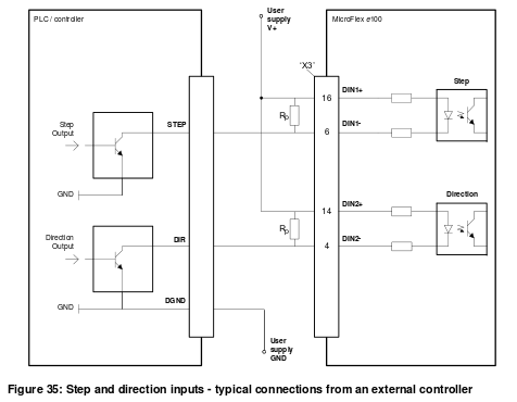
I assume you mean fig 35 which is on page 69. It is a pretty standard DIR / STEP opto isolated connection
It will be whichever connections go to a stepper driver from the on board stepgen.
Unfortunately I don't use the Mesa boards, someone else will have to fill in where the 2 missing wires come from
I think it all depends which firmware you have installed as to which pins are programmed
regards
the suggested wiring is on page 68 of the drive manual
dl.dropboxusercontent.com/u/95163186/MN1942WEN_05-12.pdf
I assume you mean fig 35 which is on page 69. It is a pretty standard DIR / STEP opto isolated connection
It will be whichever connections go to a stepper driver from the on board stepgen.
Unfortunately I don't use the Mesa boards, someone else will have to fill in where the 2 missing wires come from
I think it all depends which firmware you have installed as to which pins are programmed
regards
Please Log in or Create an account to join the conversation.
- cncbasher
- Offline
- Moderator
-

Less
More
- Posts: 1744
- Thank you received: 288
20 Jul 2013 22:05 - 20 Jul 2013 22:10 #36828
by cncbasher
Replied by cncbasher on topic wiring help
simply connect to the step and direction terminals on the 7i76
see page 5-9 of your pdf and connect as per pins 6 for step and 4 for direction , take pins 16 and 14 to 5v supply on 7i76
forget Rp it's not needed ..
7i76 connections on TB2 are:
GND 0
X STEP 2
X DIRECTION 4
Y STEP 8
Y DIRECTION 10
Z STEP 14
Z DIRECTION 16
+5v 5
see page 5-9 of your pdf and connect as per pins 6 for step and 4 for direction , take pins 16 and 14 to 5v supply on 7i76
forget Rp it's not needed ..
7i76 connections on TB2 are:
GND 0
X STEP 2
X DIRECTION 4
Y STEP 8
Y DIRECTION 10
Z STEP 14
Z DIRECTION 16
+5v 5
Last edit: 20 Jul 2013 22:10 by cncbasher.
Please Log in or Create an account to join the conversation.
- jd896
- Offline
- Premium Member
-
Less
More
- Posts: 120
- Thank you received: 0
20 Jul 2013 22:35 #36830
by jd896
Replied by jd896 on topic wiring help
just had a go like this and it didnt work ive just noticed this in the manual on page 126 - 8.1.6
active = grater than 12v
inactive = less than 2v
so how can they say it'll work at 5 ?
active = grater than 12v
inactive = less than 2v
so how can they say it'll work at 5 ?
Please Log in or Create an account to join the conversation.
- jd896
- Offline
- Premium Member
-
Less
More
- Posts: 120
- Thank you received: 0
20 Jul 2013 22:39 #36831
by jd896
Replied by jd896 on topic wiring help
this is the email from abb
Hi,
The Step and Direction inputs use the fast inputs. These are optoisolated and are really designed for 12 – 24V input signals. Although tests have been run at 5V, due to the wide range of opto parameters, operation cannot be 100% guaranteed with every single opto device, but to date we’ve not heard of any issues.
Specific timings are hard to give, but the maximum input frequency is about 1MHz, with a minimum pulse time of around 250nS. These give the Step and Step space timings. Setup and hold for Direction need to be about 100nS based on range of propagation delay through the opto input.
If these inputs are driven from an open-collector source, then a low value external pull-up is (eg 110R) needed to reduce the time constant set by the EMC filter capacitors on the input.
Pulling to a 5V supply will produce the fastest response
Pulling to a 12V supply is a safe option; it will work and have a reasonable response.
Pulling to a 24V supply will produce the slowest response.
The response frequencies etc.. are detailed in the table in the drive installation manual (attached – see Page 68).
The step and direction handling logic following the opto (i.e. the software internally) can run at much higher speeds, but the overall performance is limited by the front end optos.
I hope this helps
Regards
Stuart
Please Log in or Create an account to join the conversation.
- PCW
-

- Away
- Moderator
-
Less
More
- Posts: 19042
- Thank you received: 5255
20 Jul 2013 23:28 - 20 Jul 2013 23:29 #36832
by PCW
Replied by PCW on topic wiring help
Looking at the input circuit in the manual and the TLP115A optocoupler data sheet, It looks like it would be marginal with 5V step/dir signals so I can see why its not guaranteed with < 12V signals.
If your level shifters dont work, I would make sure that the pullup resistors are low enough (I would use about 470 Ohm 1W at 12V and 1K 2W at 24V). This is because of the drives input hash filter capacitors and the wiring capacitance
make a RC filter for the high going 12 or 24V pulse
Also since the level shifter inverts the step/dir signals you may want to use the inverted 7I76 outputs (or invert the step/dir pins in HAL)
Because of the slowness of the optocoupler input circuit I would use wide timing margins, certainly no less than 2 usec step times and idle times and similar dir setup and hold times
Last edit: 20 Jul 2013 23:29 by PCW. Reason: clarify
Please Log in or Create an account to join the conversation.
- jd896
- Offline
- Premium Member
-
Less
More
- Posts: 120
- Thank you received: 0
21 Jul 2013 00:04 #36833
by jd896
Replied by jd896 on topic wiring help
right just nipped out and have gotten 2w 1k resistors as they didnt have the 1 watt only 0.6w
so im right in thinking i now go +24v via resistor to step input then the step input ground via the 7i76 inverted pin to 24v gnd?
or do the resistors go across the drive terminals ? bettween the 24v in to the step and the step gnd ?
so im right in thinking i now go +24v via resistor to step input then the step input ground via the 7i76 inverted pin to 24v gnd?
or do the resistors go across the drive terminals ? bettween the 24v in to the step and the step gnd ?
Please Log in or Create an account to join the conversation.
- PCW
-
- Away
- Moderator
-
Less
More
- Posts: 19042
- Thank you received: 5255
21 Jul 2013 01:17 - 21 Jul 2013 02:14 #36837
by PCW
Replied by PCW on topic wiring help
arceyes picture is correct:
+24 to drive 14,16 (DIN+) and one side of pullup resistors
other side of pullup resistors go to drive 4,5 (DIN-)
and level shifter (UDN2982?) outputs
7I76 step/dir outputs go the level shifter inputs
7I76 gnd goes to level shifter gnd
+24 to drive 14,16 (DIN+) and one side of pullup resistors
other side of pullup resistors go to drive 4,5 (DIN-)
and level shifter (UDN2982?) outputs
7I76 step/dir outputs go the level shifter inputs
7I76 gnd goes to level shifter gnd
Last edit: 21 Jul 2013 02:14 by PCW.
The following user(s) said Thank You: jd896
Please Log in or Create an account to join the conversation.
- jd896
- Offline
- Premium Member
-
Less
More
- Posts: 120
- Thank you received: 0
22 Jul 2013 18:55 #36882
by jd896
Replied by jd896 on topic wiring help
Does this mean the udn2982 is the wrong chip as this is a sourcing driver
Do I now need some thing like a uln2803 an open collector driver ?
Please note building circuits is not my strong point buy far as the level shifter was The first thing I've done and that didn't have the success I would have liked
So if there are any more suited chips for the purpose then please recommend them
Many thanks John
Please Log in or Create an account to join the conversation.
- PCW
-
- Away
- Moderator
-
Less
More
- Posts: 19042
- Thank you received: 5255
22 Jul 2013 21:32 #36890
by PCW
Replied by PCW on topic wiring help
Sorry, I had forgotten that the UDN2982 was a sourcing driver. It should work fine but the wiring will be different:
Drive pins 4 and 6 (DIN-) to 24V GND. +24V to UDN 2982 Vs (pin 9)
Drive pins 14,16 (DIN+) connect to UDN2982 outputs and one side
of pulldown resistors. Common side of pulldown resistors goes to
24V GND.
7I76 step/dir outputs to UDN2982 inputs. 7I76 GND to UDN2982 GND
24V GND to UDN2982 GND
Drive pins 4 and 6 (DIN-) to 24V GND. +24V to UDN 2982 Vs (pin 9)
Drive pins 14,16 (DIN+) connect to UDN2982 outputs and one side
of pulldown resistors. Common side of pulldown resistors goes to
24V GND.
7I76 step/dir outputs to UDN2982 inputs. 7I76 GND to UDN2982 GND
24V GND to UDN2982 GND
Please Log in or Create an account to join the conversation.
Moderators: PCW, jmelson
Time to create page: 0.086 seconds