simple and cheap stepper motor drives for DIY-ers
- tommylight
-
 Topic Author
- Away
- Moderator
-

Less
More
- Posts: 20604
- Thank you received: 7009
05 Apr 2015 06:22 - 26 Dec 2015 01:25 #57537
by tommylight
simple and cheap stepper motor drives for DIY-ers was created by tommylight
This is some copy/paste action from a post i started at cnczone.com.
Let's start with a warning : everything mentioned below is for experimenting and testing purposes, and a great tool to learn a lot about electronics and stepper motors and LinuxCNC, so inadvertantly it uses power, electricity, small gremlins and other magic to make thing work and motors turn and machines producing ....art or something, and as with everything that uses electricity be carefull, use common sense and check everything before switching on the power. That beeing said, i am not liable or responsible for anything that might happen while using this article like: blowing your house up, seting it on fire, getting yourselfs elctrocuted ( not a nice feeling ) or killed etc etc.
Here are the schematics and explanations for the folowing:
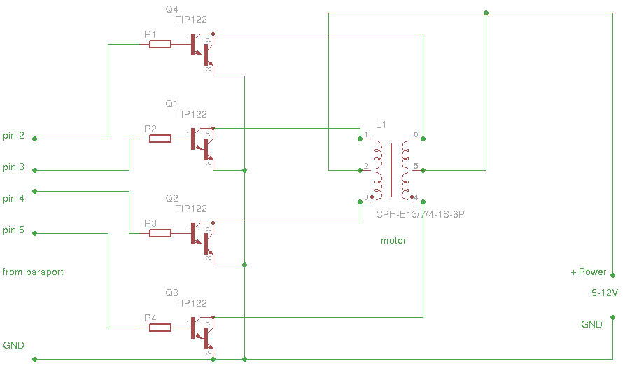
This is the easiest drive to build requiring only 4 NPN darlington transistors, TIP122 or anything that can handle VCE of at least 50V and current of anything above 3A, and 4 resistors of 100-470 Ohm resistance. The resistors should be connected to inputs from parallel port at pins 2, 3, 4, 5 and the other side connected to the base of respective transistors. All Emiters from the transistors are connected to ground or negative of power supply. Colectors from the transisttors should be connected to one of the motor windings, beware the motors must be unipolar, so anything with 5, 6, or 8 wires can do just fine. The center tap of the motor go to the positive side of the power supply. Power supply should be from 5Vto 12V and that depends on the motors used. For experimenting, a mobile phone charger or an acces point/router power supply will do just fine for driving a single motor. Do not get discouraged if the motor does not start turning at first try, the windings have to be connect at an order, so switch of the power supply and change places on the motor wires, 2 at a time so you can keep track at what combination did not work.Do this untill you get rotation on both sides.
Moving on
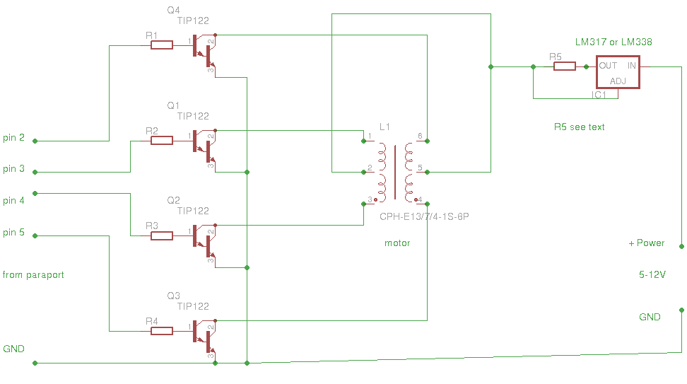
This is the same thing with the added current limiter, so it is posible to use much higher voltages and achieve faster rotation speeds. All the above aplies to this with the exeption of using a power supply capable of anything from 12V to 30V, even 37V if you are feeling lucky.
The voltage regulators used are LM317 or LM338. LM317 can supply currents from 500mA to 1A so the resistor R5 should be 1.2-1.5 Ohm 2W for 750mA to 1A current or 2.4-2.5 Ohm for 500mA. Same goes for LM338 but the resistor can be 0.6Ohm for 2A or 0.33Ohm for 4A of current.
The voltage regulators must be atached to a bigger heat sink, old computer coolers will do perfect.
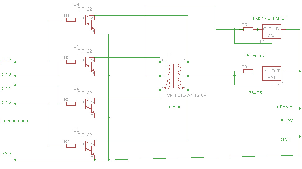
Again, this is the same as above exept it uses 2 voltage regulators for each side of the motor windigs so if using LM317 you can get up to 1A per winding of the motor. R6 is the same as R5 mentioned above. In this case only motors with 6 or 8 wires can be used.
All versions above use the same config for LinuxCNC in the atachment on post #2, and all can be configured to run at full step (default config) or at half step ( se LinuxCNC HAL manual for other types of stepgen_type for editing the core_stepper.hal file in the atachment ).
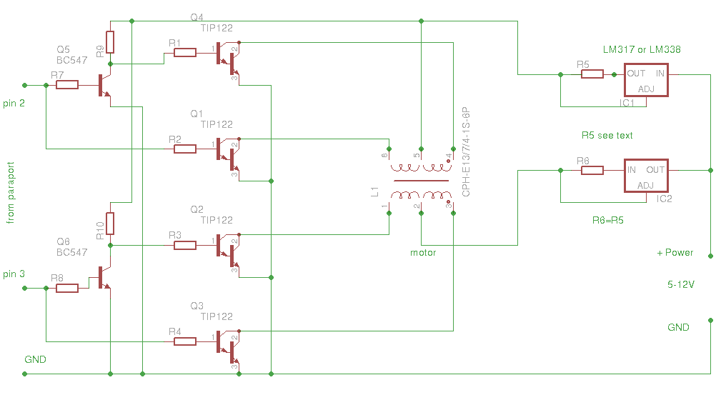
This is a bit more complicated and has 2 limiters, but it uses only 2 outputs from parallel port for one motor. It has included limiters for both motor windings and they can be left out as explained above. All input resistors can be from 330-680 Ohm. The 2 added transistors can be smal signal transistors like BC337, BC547, 2N2222 or similar.
This one uses the atached config, that has stepgen_type set as 2 for a quadrature output on pins 2 and 3 for the first motor or X axes. Pins 3 and 4 are Y and pins 5 and 6 are Z.
Again this is ment for experimenting and learning, but can be used on hobby machines succesfuly.
Regards, oh please do let us know if you blow something up or if it works.
Tom
EDIT:
On pictures 3 and 4 the IC2 should be mirrored as is IC1, the input and output pins are reversed.
Let's start with a warning : everything mentioned below is for experimenting and testing purposes, and a great tool to learn a lot about electronics and stepper motors and LinuxCNC, so inadvertantly it uses power, electricity, small gremlins and other magic to make thing work and motors turn and machines producing ....art or something, and as with everything that uses electricity be carefull, use common sense and check everything before switching on the power. That beeing said, i am not liable or responsible for anything that might happen while using this article like: blowing your house up, seting it on fire, getting yourselfs elctrocuted ( not a nice feeling ) or killed etc etc.
Here are the schematics and explanations for the folowing:
This is the easiest drive to build requiring only 4 NPN darlington transistors, TIP122 or anything that can handle VCE of at least 50V and current of anything above 3A, and 4 resistors of 100-470 Ohm resistance. The resistors should be connected to inputs from parallel port at pins 2, 3, 4, 5 and the other side connected to the base of respective transistors. All Emiters from the transistors are connected to ground or negative of power supply. Colectors from the transisttors should be connected to one of the motor windings, beware the motors must be unipolar, so anything with 5, 6, or 8 wires can do just fine. The center tap of the motor go to the positive side of the power supply. Power supply should be from 5Vto 12V and that depends on the motors used. For experimenting, a mobile phone charger or an acces point/router power supply will do just fine for driving a single motor. Do not get discouraged if the motor does not start turning at first try, the windings have to be connect at an order, so switch of the power supply and change places on the motor wires, 2 at a time so you can keep track at what combination did not work.Do this untill you get rotation on both sides.
Moving on
This is the same thing with the added current limiter, so it is posible to use much higher voltages and achieve faster rotation speeds. All the above aplies to this with the exeption of using a power supply capable of anything from 12V to 30V, even 37V if you are feeling lucky.
The voltage regulators used are LM317 or LM338. LM317 can supply currents from 500mA to 1A so the resistor R5 should be 1.2-1.5 Ohm 2W for 750mA to 1A current or 2.4-2.5 Ohm for 500mA. Same goes for LM338 but the resistor can be 0.6Ohm for 2A or 0.33Ohm for 4A of current.
The voltage regulators must be atached to a bigger heat sink, old computer coolers will do perfect.
Again, this is the same as above exept it uses 2 voltage regulators for each side of the motor windigs so if using LM317 you can get up to 1A per winding of the motor. R6 is the same as R5 mentioned above. In this case only motors with 6 or 8 wires can be used.
All versions above use the same config for LinuxCNC in the atachment on post #2, and all can be configured to run at full step (default config) or at half step ( se LinuxCNC HAL manual for other types of stepgen_type for editing the core_stepper.hal file in the atachment ).
This is a bit more complicated and has 2 limiters, but it uses only 2 outputs from parallel port for one motor. It has included limiters for both motor windings and they can be left out as explained above. All input resistors can be from 330-680 Ohm. The 2 added transistors can be smal signal transistors like BC337, BC547, 2N2222 or similar.
This one uses the atached config, that has stepgen_type set as 2 for a quadrature output on pins 2 and 3 for the first motor or X axes. Pins 3 and 4 are Y and pins 5 and 6 are Z.
Again this is ment for experimenting and learning, but can be used on hobby machines succesfuly.
Regards, oh please do let us know if you blow something up or if it works.
Tom
EDIT:
On pictures 3 and 4 the IC2 should be mirrored as is IC1, the input and output pins are reversed.
Last edit: 26 Dec 2015 01:25 by tommylight.
Please Log in or Create an account to join the conversation.
Moderators: PCW, jmelson
Time to create page: 0.100 seconds