Problems with 7i76e setup
- deawe
- Offline
- New Member
-

- Posts: 13
- Thank you received: 1
This file can be posted to a web site like:
     http://pastebin.com
in order to provide information about the linuxcnc
system and configuration.

VIEWER=mousepad
                Date: Sat Apr 1 13:24:30 EEST 2017
            UTC Date: Sat Apr 1 10:24:30 UTC 2017
        this program: /usr/bin/linuxcnc_info
              uptime: 13:24:30 up 7 min, 1 user, load average: 1.12, 0.80, 0.40
     lsb_release -sa: Debian Debian GNU/Linux 7.11 (wheezy) 7.11 wheezy
      which linuxcnc: /usr/bin/linuxcnc
                 pwd: /home/dea
                USER: dea
             LOGNAME: dea
                HOME: /home/dea
              EDITOR:
              VISUAL:
            LANGUAGE: en_US:en
                TERM: xterm
           COLORTERM: Terminal
             DISPLAY: :0.0
        display size: 1280x1024 pixels (338x270 millimeters)

uname items:
         nodename -n: linuxcnc
      kernel-name -s: Linux
      kernel-vers -v: #1 SMP PREEMPT RT Debian 3.2.86-1
          machine -k: linuxcnc
        processor -p: unknown
         platform -i: unknown
      oper system -o: GNU/Linux

/proc items:
             cmdline: BOOT_IMAGE=/boot/vmlinuz-3.2.0-4-rt-686-pae root=UUID=2198db8f-3994-42a7-a495-4e348482a949 ro initrd=/install/gtk/initrd.gz lapic quiet rootdelay=5
          model name: Intel(R) Core(TM)2 CPU 4300 @ 1.80GHz
               cores: 2
             cpu MHz: 1200.000
             parport: e000-e002 : parport1 e003-e007 : parport1 ec00-ec02 : parport0
              serial: 03f8-03ff : serial

Varsions:
                 gcc: gcc (Debian 4.7.2-5) 4.7.2
              python: Python 2.7.3
                 git: git version 1.7.10.4
                 tcl: 8.5
                  tk: 8.5
               glade: not_in_PATH
          glade-gtk2: glade3 3.8.0

linuxcnc_var all:

     LINUXCNCVERSION: 2.7.8
            REALTIME: /etc/init.d/realtime
                 RTS: uspace
          HALLIB_DIR: /usr/share/linuxcnc/hallib
Please Log in or Create an account to join the conversation.
- PCW
-

- Offline
- Moderator
-

- Posts: 17954
- Thank you received: 5261
Please Log in or Create an account to join the conversation.
- deawe
- Offline
- New Member
-
- Posts: 13
- Thank you received: 1
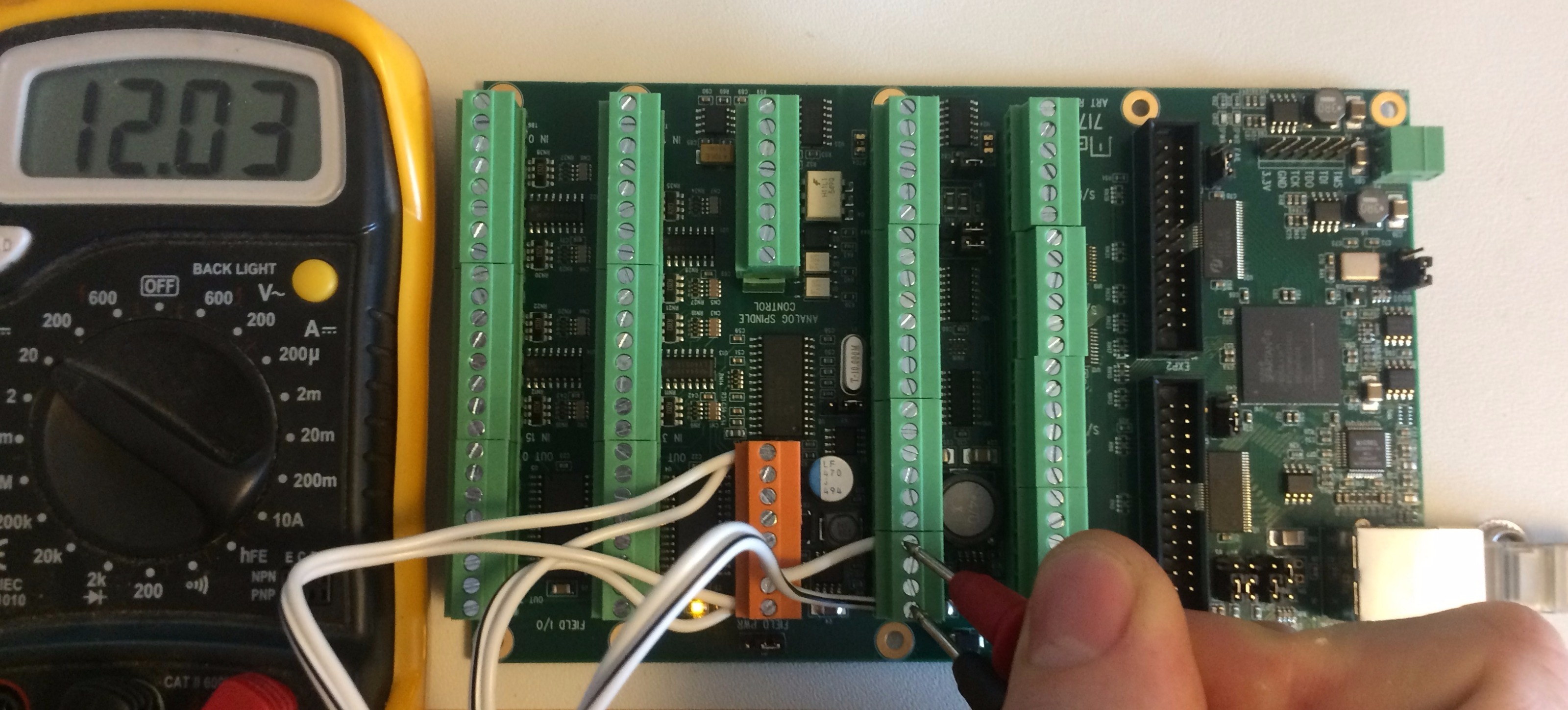
To conclude this I have attached a photo of the board powered through the TB3 terminal. The field power LED is lit and visible through the leads, but the logic power LED does not turn on. I guess we can agree then that the board is faulty? And for reference, the board is resting on an ESD mat, and have been so ever since I took it out of the bag it was delivered in.
Please Log in or Create an account to join the conversation.
- tommylight
-

- Away
- Moderator
-
- Posts: 21691
- Thank you received: 7414
Please Log in or Create an account to join the conversation.
- deawe
- Offline
- New Member
-
- Posts: 13
- Thank you received: 1
According to the 7i76e manual: "If you wish to use a single power supply for the 7I76Es field outputs and field logic power, W1 should be placed in the left hand position. This connects field power to VIN." It's possible to make out the position of the jumper below the yellow TB1 connector in the photo I attached. The jumper positions in the manual refer to the board oriented with the RJ-45 connector on the left-hand side, so the photo has to be rotated 180 degrees to correspond to that.
In any case, I would not think that the field power jumper would affect the supply to the logic section of the card.
Please Log in or Create an account to join the conversation.
- PCW
-
- Offline
- Moderator
-
- Posts: 17954
- Thank you received: 5261
with the order number and description of problem and the card can be returned for repair/replacement
Please Log in or Create an account to join the conversation.
- rodw
-

- Offline
- Platinum Member
-

- Posts: 11986
- Thank you received: 4083
I've attached a very useful wiring diagram for the 7i76e uploaded to the forum by another member.
I have deviated from this setup which seems the same as yours becasue I have applied 5 volt power to P5. That means W1 jumper needs to be changed. Just note that if you use the MPG encoder inputs, you need to tie the GNDs together as per the note on Page 2.
If it is a faulty regulator, perhaps P5 will let you get the board going.
Please Log in or Create an account to join the conversation.
- deawe
- Offline
- New Member
-
- Posts: 13
- Thank you received: 1
rodw, thanks for the wiring diagram, that is very helpful! I have been looking for something similar, but my searches turned up empty. Do you happen to remember in which thread this was posted? It would be interesting to see a little bit more about it.
Thanks to you all for the prompt and valuable support!
Please Log in or Create an account to join the conversation.
- tommylight
-
- Away
- Moderator
-
- Posts: 21691
- Thank you received: 7414
Please Log in or Create an account to join the conversation.
- deawe
- Offline
- New Member
-
- Posts: 13
- Thank you received: 1
The card should certainly work without 5V on that connector. The following from the manual:
In the photo, I supplied power to TB3 instead.The 7I76E can get its 5V Ethernet, encoder, step/dir and serial interface power from
connector P3 or the on card logic power regulator can be used with unregulated DC power
supplied to TB3
And also a few posts back:
If you cannot run the 7I76E from correct TB3 power, you have a bad or damaged 7I76E
Please Log in or Create an account to join the conversation.