Wiring Help - PMDX-126 moving to 7i76
- racedirector
- Offline
- Elite Member
-

- Posts: 231
- Thank you received: 42
One of my triggers for an e-stop was managed somewhat by the 126 through it's "Fault" pin. My AM882 alarms where connected to this pin via a 24V relay as explained below:
For anyone using a PDMX bob FAULT input (J13) they should connect the AM882's as in the diagram using a relay, then connect the normally closed NC contacts of the relay to the PDMX FAULT (J13) input and Gnd(J13)
This means when the relay is energised the PDMX Fault input will be High (floating) and LOW when the relay is de-energised (connected to Gnd)
From the PDMX manual;
"The Fault input provides an interface for external fault detection circuits. This signal is “active low”, meaning that a logic “low” (or ground) indicates a fault condition, and a logic high (or floating)
means “all is OK”.
The other trigger for an e-stop comes via a PNOZ-1 safety relay to which all of my mushroom e-stop switches are connected. There is one wire that runs from the PNOZ to the e-stop pin on the 126. the 126 E-stop is explained as:
6.3 E-Stop Input
The E-Stop input on connector J13 provides an interface for external “emergency stop” circuits. This signal is “active high”, such that a logic “high” tells the system to stop, and a logic “low” means “all is OK.” See section 6.7 for information on how the PMDX-126 filters the E-Stop input. The E-Stop input has an internal pull-up resistor so that the default condition is “E-Stop”. This also means that the external emergency stop circuit must be capable of sinking at least 6 mA of current when the switch contacts are “closed”.
NOTE: The E-Stop signal must be grounded (or driven low) in order for the PMDX-126’s outputs to be enabled, and for the pin 10 status signal to the PC parallel port to go low. If you do not have an E-Stop switch or circuit then install a jumper wire between the “E-Stop” terminal and the “GND” terminal on connector J13 (the board ships with this jumper wire installed).
6.7 E-Stop, Fault and Error Input Filtering
The PMDX-126 filters the E-Stop, Fault and Error inputs to help eliminate noise from causing false E-Stop conditions. These inputs are sampled 1250 times per second and must remain active for 64 consecutive samples (approximately 50 ms) in order for the PMDX-126 to declare them “active” and disable its outputs and assert the E-Stop signal to the PC. Once a signal is determined to be “active”, it will go “inactive” on the first sample where the input signal is inactive. That means that the active-going transition is filtered, but the inactive transition is not.
Note that the E-Stop and Fault inputs are combined into a single signal and THEN sampled by the noise filter.
One thing I do not understand is the 7i76 inputs are "sinking" inputs, what are "sinking" inputs? For that matter what are "sourcing" outputs?
I am asking this because I just got my MESA cards connected to my machine and Axis won't come out of e-stop, so I am obviously missing something or doing something wrong. I have no problem rewiring my control box, that is if I know what I am doing. Getting out of e-stop will be the first hurdle to cross....
Any help would be greatly appreciated.
Please Log in or Create an account to join the conversation.
- rodw
-

- Offline
- Platinum Member
-

- Posts: 12005
- Thank you received: 4086
forum.linuxcnc.org/10-advanced-configura...latches?limitstart=0
If you want a fault signal, you could remove one step in the chain. (but what triggers a fault? maybe it is ignored)
Also, here is a simpler example with just an estop switch
gnipsel.com/linuxcnc/configs/external-estop.html
The 7i76e inputs needs say 24 volts applied to it to make it true or on. Normally your estop button will be normally closed so the pin will be true and turn false if there is an error. so you would pick up 24v, run it to your switch and then back to the input.
I would start with your multimeter and make sure you know the state on estop at the input and then confirm that is happening in halshow when you press the button. Then set the hal code accordingly. get your estop working first probably with the tutorial code above and then add any extra fault inputs. Remember, you may need to use the input-not
Please Log in or Create an account to join the conversation.
- racedirector
- Offline
- Elite Member
-
- Posts: 231
- Thank you received: 42
I had an "aha" monet earlier tonight after RTFM that the 7i76 needs a voltage to detect conditions. As you have just confirmed I need to run my 24V line out and back to the 7i76 for it to notice. Was just in the shed trying to figure out my wiring as I can't find my damn diagram I made over 2 years ago, thats what you get for changing computers in that time.
I'll take a closer look at your thread, I probably skimmed over about a dozen of them and got myself all tied up knots. Time to take a breath and start again.
Thanks so much for the input, I needed that kind of a kick in the pants.
Cheers
Please Log in or Create an account to join the conversation.
- rodw
-
- Offline
- Platinum Member
-
- Posts: 12005
- Thank you received: 4086
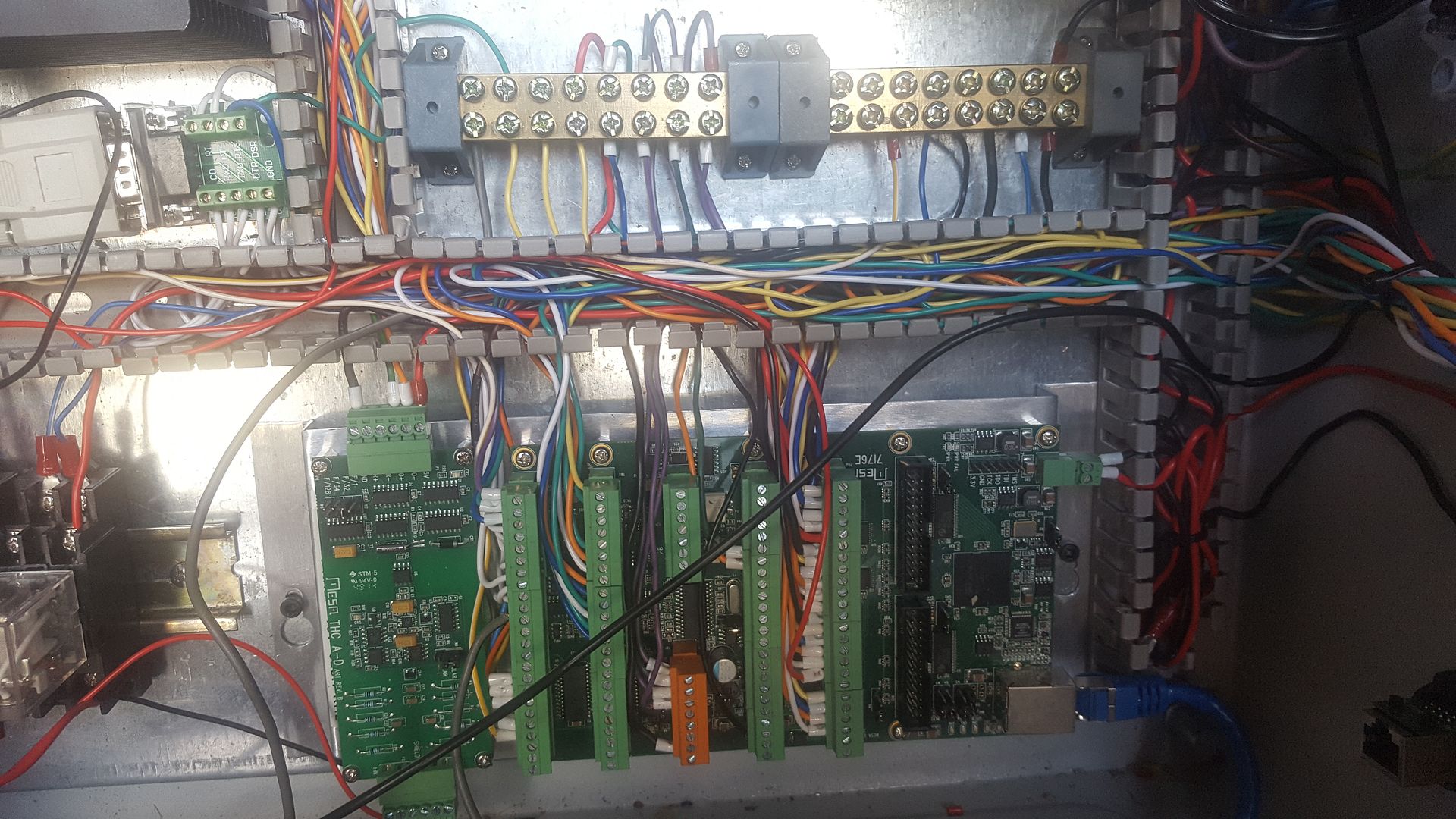
One on the left is +24 volt right one is -24v
I wondered why I put one in for -24v. it just seems to get used if there is a relay involved.
Jaycar do have a smaller BUS bar but you can see th e+24V is well used...
Please Log in or Create an account to join the conversation.
- racedirector
- Offline
- Elite Member
-
- Posts: 231
- Thank you received: 42
With mine i have the 24v going to gang connectors first then off to my 7i76. Probably doesn't matter but I thought I'd ask
Cheers
Please Log in or Create an account to join the conversation.
- rodw
-
- Offline
- Platinum Member
-
- Posts: 12005
- Thank you received: 4086
Please Log in or Create an account to join the conversation.
- racedirector
- Offline
- Elite Member
-
- Posts: 231
- Thank you received: 42
Have got software e-stop working now, just need to get the hardware talking to software.
I also got Z and Y moving, I have to say that I have never seen my machine do 1500 inches per minute before without hiccup but bloody hell its fast. Y traverses 1250mm REAL quick at that speed. Time to adjust a few thing I think.
Please Log in or Create an account to join the conversation.
- rodw
-
- Offline
- Platinum Member
-
- Posts: 12005
- Thank you received: 4086
Please Log in or Create an account to join the conversation.