Meas THCAD-10 noisy signal
- rodw
-
 Topic Author
- Offline
- Platinum Member
-

Less
More
- Posts: 11557
- Thank you received: 3877
02 Sep 2017 04:39 #98356
by rodw
Meas THCAD-10 noisy signal was created by rodw
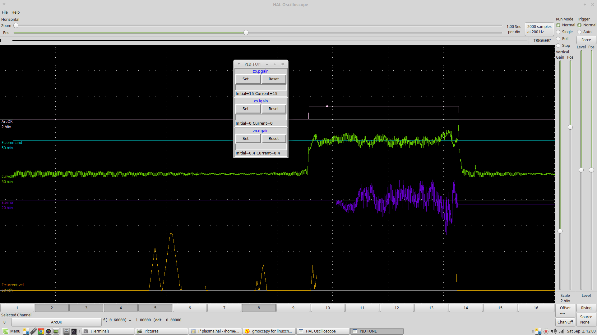
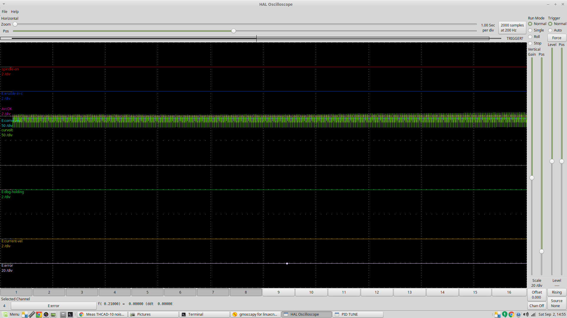
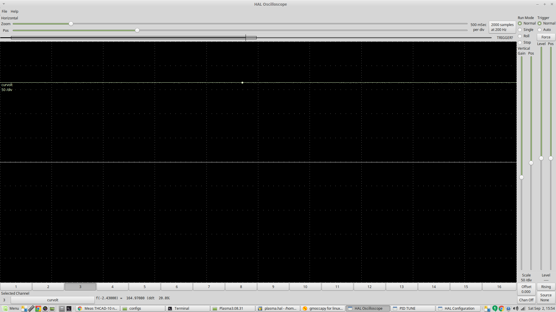
I've using the THCAD-10 (using 1/32 division) with an external resistor to double the full scale range to 20 volts. This proved too much so I removed it to revert to the native 10 volt scale and the signal became very noisy:
So with the plasma cutter turned off, I connected 2 x 48 volt power supplies together and connected them to the internal CNC board.
The board has a 100 k resistor on both the +ve and -ve raw arc signals so the raw output voltage measured 94.4 volts.
The divided voltage on the 16:1 divider is showing 5.91 volts which is 15:97:1
Previously, the voltage signal in LinuxCNC was very stable
As soon as I plug the divided signals into the THCAD-10, the voltage observed becomes 2.943 volts and this is what is sent to Linuxcnc. So the divider is 32:076:1
I am guessing the divider circuit on the Plasma CNC board are seen by the THCAD-10 as being external resistors. I can calibrate that out with my test signal.
With the plasma cutter turned off, there is no noise source.
So why is the noise there all of a sudden and how can I manage it? The signal is unusable as it stands.
Please Log in or Create an account to join the conversation.
- PCW
-

- Offline
- Moderator
-

Less
More
- Posts: 17478
- Thank you received: 5106
02 Sep 2017 04:47 #98357
by PCW
Replied by PCW on topic Meas THCAD-10 noisy signal
Looks like maybe a missing ground
Please Log in or Create an account to join the conversation.
- rodw
-
 Topic Author
- Offline
- Platinum Member
-

Less
More
- Posts: 11557
- Thank you received: 3877
02 Sep 2017 04:50 #98358
by rodw
Replied by rodw on topic Meas THCAD-10 noisy signal
What side Peter the plasma side of the Meas 7i76e side?
Please Log in or Create an account to join the conversation.
- rodw
-
 Topic Author
- Offline
- Platinum Member
-

Less
More
- Posts: 11557
- Thank you received: 3877
02 Sep 2017 04:58 #98359
by rodw
Replied by rodw on topic Meas THCAD-10 noisy signal
Please Log in or Create an account to join the conversation.
- rodw
-
 Topic Author
- Offline
- Platinum Member
-

Less
More
- Posts: 11557
- Thank you received: 3877
02 Sep 2017 05:15 - 02 Sep 2017 05:15 #98361
by rodw
Replied by rodw on topic Meas THCAD-10 noisy signal
Last edit: 02 Sep 2017 05:15 by rodw.
Please Log in or Create an account to join the conversation.
- PCW
-

- Offline
- Moderator
-

Less
More
- Posts: 17478
- Thank you received: 5106
02 Sep 2017 05:36 #98362
by PCW
Replied by PCW on topic Meas THCAD-10 noisy signal
I would think this is an issue on the analog side (Input shield not connected to frame ground, input ground not connected to plasma ground etc)
why is the sample rate so slow (200 Hz)? can you speed up the sweep so the oscillation/noise can be resolved a little better?
why is the sample rate so slow (200 Hz)? can you speed up the sweep so the oscillation/noise can be resolved a little better?
Please Log in or Create an account to join the conversation.
- rodw
-
 Topic Author
- Offline
- Platinum Member
-

Less
More
- Posts: 11557
- Thank you received: 3877
02 Sep 2017 06:06 #98363
by rodw
Replied by rodw on topic Meas THCAD-10 noisy signal
Peter thanks.
It clearly is on the plasma side. I did a plot of the 5 volt on the stepgen voltages and it was perfect. Clean and exactly where they should be.
The 200 hz signal is a default becasue there are 8 signals being monitored as part of Deweys eoffset_pid so I'll enlarge it on the next plot.
I will checkout the grounds. I'm using a 9 core shielded plasma interconnect cable. At the control box end, the cable shield is connected to one of the Shield inputs. The other shield input goes to frame ground (nice copper stud on the enclosure).
At the plasma end, the shield is not terminated anywhere which is how I thought it should be done.
Please Log in or Create an account to join the conversation.
- rodw
-
 Topic Author
- Offline
- Platinum Member
-

Less
More
- Posts: 11557
- Thank you received: 3877
02 Sep 2017 06:32 #98364
by rodw
Replied by rodw on topic Meas THCAD-10 noisy signal
Here's a wiring pic inside of the cabinet. Everything seems perfect here (except the loose wires are from my 5 volt pins from a stepgen).
Frame ground connected from THCAD to stud on right above vent.
Plasma interconnect socket is the large circular one directly above the THCAD. Shield comes through on one pin and is connected back to the shield in the short piece of cable and on to the other THCAD frame ground connector pin. There is continuity from the shield outside the case to the silver mounting base (and the copper stud) so it checks out OK.
There is nothing special about the CNC board in the plasma cutter
The large connector goes to the socket the plasma interconnect cable attaches.
You can see the connection to the plasma has been removed from the small connector and my test power supply is connected to the raw arc voltage + and - pins. I've spent hours drawing out this circuit board due to other issues.. the raw arc voltage simply goes straight to the resistor bank. There are no other components.
Please Log in or Create an account to join the conversation.
- rodw
-
 Topic Author
- Offline
- Platinum Member
-

Less
More
- Posts: 11557
- Thank you received: 3877
02 Sep 2017 07:13 #98366
by rodw
Replied by rodw on topic Meas THCAD-10 noisy signal
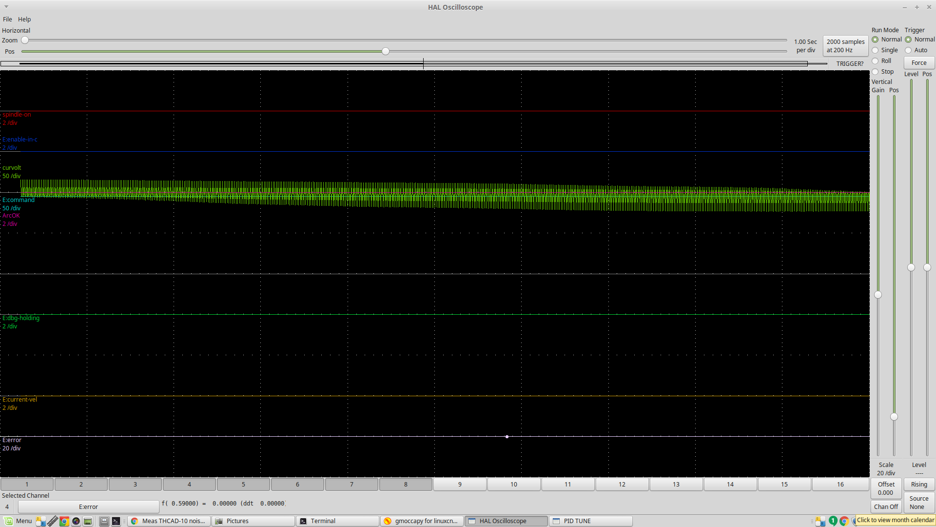
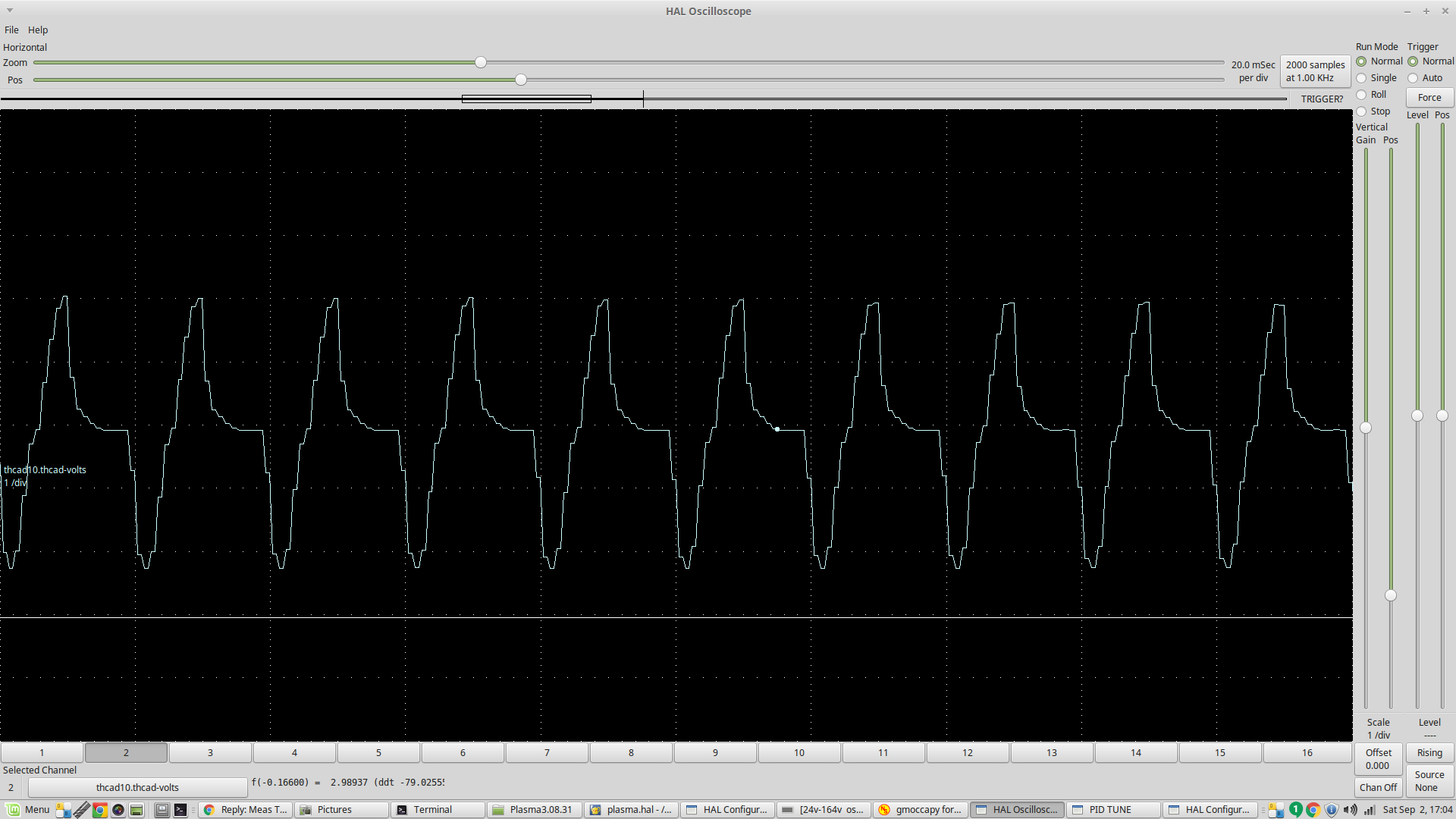
I thought it was best to give a plot of the actual volts in the 0-10 volt range.
I think this has got worse. there is a bit over a 4 volt range peak to trough.
There's at best a 0.010 volt variation on the plasma side of the THCAD according to my multimeter (which might not be the greatest but it has a 0.001V scale and 4000 counts) There is nothing to generate noise as the plasma is not powered up. Very strange.
Please Log in or Create an account to join the conversation.
- PCW
-

- Offline
- Moderator
-

Less
More
- Posts: 17478
- Thank you received: 5106
02 Sep 2017 13:31 #98371
by PCW
Replied by PCW on topic Meas THCAD-10 noisy signal
50 Hz...
Is that your line frequency?
The mulltimeter will average the signal on DC what does the multimeter read on AC?
Is that your line frequency?
The mulltimeter will average the signal on DC what does the multimeter read on AC?
Please Log in or Create an account to join the conversation.
Moderators: PCW, jmelson
Time to create page: 0.273 seconds

