Open Collector To Line driver
- bkt
-
 Topic Author
- Offline
- Platinum Member
-

Less
More
- Posts: 1111
- Thank you received: 114
08 Jun 2018 17:15 #112011
by bkt
Open Collector To Line driver was created by bkt
He At all ...
I'm a very poor electronics boy, so I'm not sure about these situation.
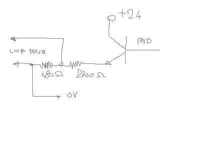
I have a plc PNP output +24V that can drive an axis in Puls Dir mode .... but it is open collector and my drive receive only Line Driver 5V signal .... so I came up with the idea of doing a simulation of the line driver communication as seen in the poor design attached .... I'm doing right or I will not get any results?
the schemas:
I need someone can check my work.
regards
Giorgio
Please Log in or Create an account to join the conversation.
- PCW
-

- Away
- Moderator
-

Less
More
- Posts: 17705
- Thank you received: 5177
08 Jun 2018 19:28 #112015
by PCW
Replied by PCW on topic Open Collector To Line driver
A line driver input will need to have a positive and negative difference between the input pins to recognize both states.
One way to do this if driven from a single ended source is to tie one of the differential inputs to a 2.5V reference
(made with 2 low value resistors (say 47 ohms x2 ) and a 5V source) Then if the other differential input is driven from
0 or 5V the difference between differential inputs pins is +2.5V or -2.5V
The following user(s) said Thank You: bkt
Please Log in or Create an account to join the conversation.
- bkt
-
 Topic Author
- Offline
- Platinum Member
-

Less
More
- Posts: 1111
- Thank you received: 114
09 Jun 2018 06:10 #112055
by bkt
Replied by bkt on topic Open Collector To Line driver
@PCW so my error is to tie one differential input to 0,xx V and not to a 2,5V?
My schems is 24V powered, but with these resistor perform 0,xxV at +ref input when plc output have no signal, and +5V at +ref input when plc perform the signal. -ref is always at 0V. So in differential mode it should be 0,xx down, 4.xx up and so on .... these is right or not?
Anyhow hanks for your reply.
regards
Giorgio
Please Log in or Create an account to join the conversation.
- billykid
-

- Offline
- Platinum Member
-

Less
More
- Posts: 470
- Thank you received: 80
09 Jun 2018 07:26 #112056
by billykid
Replied by billykid on topic Open Collector To Line driver
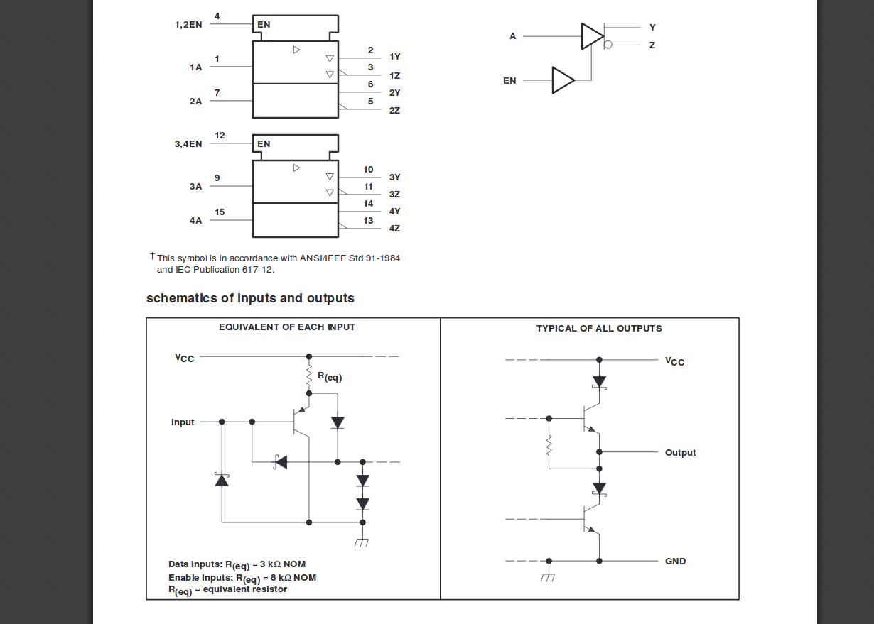
I have always used this: sn75174 or an equivalent.
regards
Mauro
regards
Mauro
The following user(s) said Thank You: bkt
Please Log in or Create an account to join the conversation.
- bkt
-
 Topic Author
- Offline
- Platinum Member
-

Less
More
- Posts: 1111
- Thank you received: 114
09 Jun 2018 08:15 - 09 Jun 2018 08:28 #112061
by bkt
Replied by bkt on topic Open Collector To Line driver
thanks .... I find only SN75174N version .... I think is the same ..... Whit these I can input my plc open collector output and obtain a normal differential output line driver is Right?
for more precision:
1) I must put Enable IN at hight level
2) use 1A channel as pulse signal from my plc
3) obtain 1Y and 1Z as puls+ & puls- signal for my ServoDrive.
Is all right?
regards
Giorgio
for more precision:
1) I must put Enable IN at hight level
2) use 1A channel as pulse signal from my plc
3) obtain 1Y and 1Z as puls+ & puls- signal for my ServoDrive.
Is all right?
regards
Giorgio
Last edit: 09 Jun 2018 08:28 by bkt.
Please Log in or Create an account to join the conversation.
- billykid
-

- Offline
- Platinum Member
-

Less
More
- Posts: 470
- Thank you received: 80
09 Jun 2018 09:58 #112067
by billykid
Replied by billykid on topic Open Collector To Line driver
Yes, right.
you can use the divider to reduce 24 volts to 5 and you're good to go.
the same for "dir"
if half do not use it, put it low en pin
regards
mauro
you can use the divider to reduce 24 volts to 5 and you're good to go.
the same for "dir"
if half do not use it, put it low en pin
regards
mauro
Please Log in or Create an account to join the conversation.
Moderators: PCW, jmelson
Time to create page: 0.123 seconds


