Mesa 7i76 spindle wiring to a Leeson Speed Master VFD
- buffcleb
- Offline
- New Member
-

Less
More
- Posts: 11
- Thank you received: 0
10 Jun 2018 02:02 - 10 Jun 2018 19:50 #112115
by buffcleb
Mesa 7i76 spindle wiring to a Leeson Speed Master VFD was created by buffcleb
I'm converting a CNC Masters Baron Mill... I have the steppers wired but am confused on how to wire the spindle to the 7i76 board...
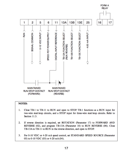
With the CNC Master's control board it used the first six pins.. Here's the wiring diagram from the manual
Any help wiring the tb4 pins to the VFD would be a huge help...
thanks
With the CNC Master's control board it used the first six pins.. Here's the wiring diagram from the manual
Any help wiring the tb4 pins to the VFD would be a huge help...
thanks
Last edit: 10 Jun 2018 19:50 by buffcleb.
Please Log in or Create an account to join the conversation.
- buffcleb
- Offline
- New Member
-
Less
More
- Posts: 11
- Thank you received: 0
10 Jun 2018 17:52 - 10 Jun 2018 18:34 #112141
by buffcleb
Replied by buffcleb on topic 7i76 spindle wiring to a Leeson Speed Master VFD
ok... I tried this wiring :
Tb4 - leeson
1 - 2
6 - 1
3 - 5
2 - 11
7 - 13a
If I enable the spindle in LinuxCNC I get nothing... so I tried jumping pins 1 to 11 on the leeson and I get forward motion... If I jumper 1, 11 and 13a I get reverse... now I need to figure out what to do next... not sure how to configure LinuxCNC to do this...
Last edit: 10 Jun 2018 18:34 by buffcleb.
Please Log in or Create an account to join the conversation.
- buffcleb
- Offline
- New Member
-
Less
More
- Posts: 11
- Thank you received: 0
10 Jun 2018 18:35 #112143
by buffcleb
Replied by buffcleb on topic 7i76 spindle wiring to a Leeson Speed Master VFD
Figured I should share my Hal file... it's stock... I've not made any changes... I can see the voltage change on the VFD between pins 2 and 5...
setp pid.s.Pgain [SPINDLE_9]P
setp pid.s.Igain [SPINDLE_9]I
setp pid.s.Dgain [SPINDLE_9]D
setp pid.s.bias [SPINDLE_9]BIAS
setp pid.s.FF0 [SPINDLE_9]FF0
setp pid.s.FF1 [SPINDLE_9]FF1
setp pid.s.FF2 [SPINDLE_9]FF2
setp pid.s.deadband [SPINDLE_9]DEADBAND
setp pid.s.maxoutput [SPINDLE_9]MAX_OUTPUT
setp pid.s.error-previous-target true
net spindle-index-enable <=> pid.s.index-enable
net spindle-enable => pid.s.enable
net spindle-vel-cmd-rpm => pid.s.command
net spindle-vel-fb-rpm => pid.s.feedback
net spindle-output <= pid.s.output
# ---digital potentionmeter output signals/setup---
setp hm2_5i25.0.7i76.0.0.spinout-minlim [SPINDLE_9]OUTPUT_MIN_LIMIT
setp hm2_5i25.0.7i76.0.0.spinout-maxlim [SPINDLE_9]OUTPUT_MAX_LIMIT
setp hm2_5i25.0.7i76.0.0.spinout-scalemax [SPINDLE_9]OUTPUT_SCALE
net spindle-output => hm2_5i25.0.7i76.0.0.spinout
net spindle-enable => hm2_5i25.0.7i76.0.0.spinena
net spindle-ccw => hm2_5i25.0.7i76.0.0.spindir
# ---setup spindle control signals---
net spindle-vel-cmd-rps <= motion.spindle-speed-out-rps
net spindle-vel-cmd-rps-abs <= motion.spindle-speed-out-rps-abs
net spindle-vel-cmd-rpm <= motion.spindle-speed-out
net spindle-vel-cmd-rpm-abs <= motion.spindle-speed-out-abs
net spindle-enable <= motion.spindle-on
net spindle-cw <= motion.spindle-forward
net spindle-ccw <= motion.spindle-reverse
net spindle-brake <= motion.spindle-brake
net spindle-revs => motion.spindle-revs
net spindle-at-speed => motion.spindle-at-speed
net spindle-vel-fb-rps => motion.spindle-speed-in
net spindle-index-enable <=> motion.spindle-index-enable
# ---Setup spindle at speed signals---
sets spindle-at-speed true
Please Log in or Create an account to join the conversation.
- PCW
-

- Offline
- Moderator
-

Less
More
- Posts: 17954
- Thank you received: 5261
10 Jun 2018 20:30 - 10 Jun 2018 20:34 #112148
by PCW
Replied by PCW on topic 7i76 spindle wiring to a Leeson Speed Master VFD
I would wire it like this:
Note that unless you can program the VFDs pin 13 to be a direction pin rather than "run reverse",
an external relay may be needed to get bidirectional control.
Also I am assuming that the digital input reference is a positive voltage. if its ground and the run input is a positive voltage you will have to reverse TB4 pins 5 and 6
7I76      LEESON     FUNCTION
TB4.1     2          ANALOG COMMON-
TB4.2     5          ANALOG SPEED CONTROL VOLTAGE
TB4.3     6          ANALOG VOLTAGE SUPPLY (+10V)
TB4.5     1          SPINDLE ENABLE - (RUN)
TB4.6    11          SPINDLE ENABLE +
Note that unless you can program the VFDs pin 13 to be a direction pin rather than "run reverse",
an external relay may be needed to get bidirectional control.
Also I am assuming that the digital input reference is a positive voltage. if its ground and the run input is a positive voltage you will have to reverse TB4 pins 5 and 6
Last edit: 10 Jun 2018 20:34 by PCW.
The following user(s) said Thank You: buffcleb
Please Log in or Create an account to join the conversation.
- ReneCNC
- Offline
- New Member
-
Less
More
- Posts: 5
- Thank you received: 2
10 Jun 2018 20:38 #112150
by ReneCNC
Replied by ReneCNC on topic 7i76 spindle wiring to a Leeson Speed Master VFD
Hi buffcleb,
I also use a 7i76 on my machine, but i have a different VFD.
The spindle enable and direction on the 7i76 are open-collector outputs,
not sure but i think you have to connect TB4 Pin 5 and6 to VFD pin 1 and 11,
and for reverse TB4 7 and 8 to VFD 13a and 11
I also use a 7i76 on my machine, but i have a different VFD.
The spindle enable and direction on the 7i76 are open-collector outputs,
not sure but i think you have to connect TB4 Pin 5 and6 to VFD pin 1 and 11,
and for reverse TB4 7 and 8 to VFD 13a and 11
The following user(s) said Thank You: buffcleb
Please Log in or Create an account to join the conversation.
- buffcleb
- Offline
- New Member
-
Less
More
- Posts: 11
- Thank you received: 0
11 Jun 2018 01:52 #112167
by buffcleb
This worked... thank you... tested it to full rpm and verified it with one of those laser meters... Here are the programable functions on the VFD...
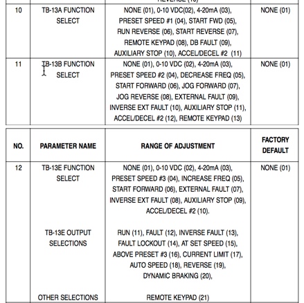
None of those seem to be a direction... so I'm going to have to figure something out...
Replied by buffcleb on topic 7i76 spindle wiring to a Leeson Speed Master VFD
I would wire it like this:
7I76      LEESON     FUNCTION
TB4.1     2          ANALOG COMMON-
TB4.2     5          ANALOG SPEED CONTROL VOLTAGE
TB4.3     6          ANALOG VOLTAGE SUPPLY (+10V)
TB4.5     1          SPINDLE ENABLE - (RUN)
TB4.6    11          SPINDLE ENABLE +
Note that unless you can program the VFDs pin 13 to be a direction pin rather than "run reverse",
an external relay may be needed to get bidirectional control.
Also I am assuming that the digital input reference is a positive voltage.if its ground and the run input is a positive voltage you will have to reverse TB4 pins 5 and 6
This worked... thank you... tested it to full rpm and verified it with one of those laser meters... Here are the programable functions on the VFD...
None of those seem to be a direction... so I'm going to have to figure something out...
Please Log in or Create an account to join the conversation.
- PCW
-
- Offline
- Moderator
-
Less
More
- Posts: 17954
- Thank you received: 5261
11 Jun 2018 13:52 #112191
by PCW
Replied by PCW on topic 7i76 spindle wiring to a Leeson Speed Master VFD
Do you have a link to a PDF version of the manual?
Please Log in or Create an account to join the conversation.
- buffcleb
- Offline
- New Member
-
Less
More
- Posts: 11
- Thank you received: 0
11 Jun 2018 14:13 #112192
by buffcleb
Replied by buffcleb on topic 7i76 spindle wiring to a Leeson Speed Master VFD
Please Log in or Create an account to join the conversation.
- Todd Zuercher
-

- Offline
- Platinum Member
-

Less
More
- Posts: 4753
- Thank you received: 1458
11 Jun 2018 17:25 #112203
by Todd Zuercher
Replied by Todd Zuercher on topic 7i76 spindle wiring to a Leeson Speed Master VFD
Those look just like the Lenze AC-tech drives I have on a couple machines. (I'm using Modbus to control those.)
Please Log in or Create an account to join the conversation.
- buffcleb
- Offline
- New Member
-
Less
More
- Posts: 11
- Thank you received: 0
11 Jun 2018 18:57 #112213
by buffcleb
Replied by buffcleb on topic 7i76 spindle wiring to a Leeson Speed Master VFD
yeah I would say the Lenze AC-tech SCM series are the same as the Leeson Speed Master VFD's... I don't see anything in the PDF about Modbus... I'll hunt around as see what I can find... maybe there's another manual about it...
Please Log in or Create an account to join the conversation.
Moderators: PCW, jmelson
Time to create page: 0.444 seconds