Troubleshooting USB-RS485 Module
- TannerFrisby
-
 Topic Author
- Offline
- Junior Member
-

Less
More
- Posts: 24
- Thank you received: 10
14 Oct 2020 00:07 #186043
by TannerFrisby
Troubleshooting USB-RS485 Module was created by TannerFrisby
Hello All,
Hardware:
I have a Teco L510 VFD which is controlled using RS485. I am using the ubiquitous USB-RS485 adapter to interface between my computer and VFD.
Issue:
It had been working as I would have expected it to until very recently when I relocated my computer. My spindle would not turn on and Hal Meter showed "no communication".
Debugging:
I figured I had snapped one of the fragile ethernet lines and that appeared to be the culprit. I resoldered and re-strain relieved my dongle, but that didn't fix the issue. I verified continuity and correct polarity. I used Windmill ComDebug on my windows laptop to send a single command. The VFD received the command and reacted appropriately, but did not return a response. Similarlly, I was able to increase and decrease speed using the Axis Gui Manual mode (but not change direction for some reason). I chalked it up to a faulty USB dongle and ordered a new one.
I wired the replacement dongle today and tested again with my laptop. The replacement dongle both sent and received a packet (as expected). I successfully homed, turned on the spindle, edgefound, turned off the spindle, tool changed, and then ran 2 programs.
I don't remember the exact sequence of events, but I did close Axis GUI while the spindle was on. The spindle continued to run for ~25 sec (the VFD window for time-out, will adjust shorter later), and then turned off when the VFD errored out. I then killed mains power to my control box. 30min-1hr later, I turned back on to run a new program. After rehoming, I was unable to ever get the spindle spinning again. Hal Meter showed no communication. I verified continuity from the dongle to the VFD. My laptop recognized the CH340 on Com3 and "sent" a packet, but the packet did not elicit a reaction or packet response from the VFD. It appears a second USB dongle is dead.
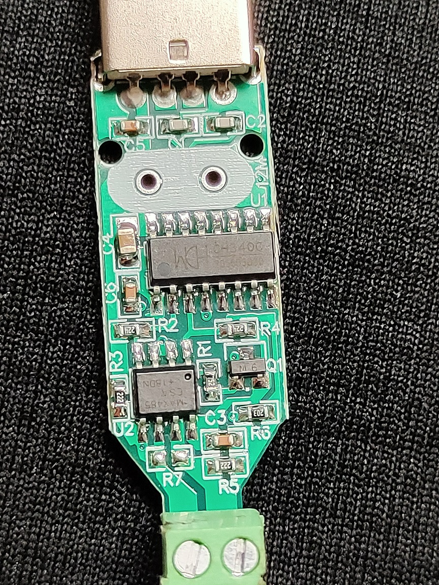
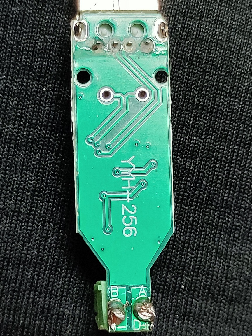
Attached are the pictures of the first dongle. I couldn't find any glaring issues (except the ommission of an oscilator!?!)
My Request:
I have ordered 4 more to be in by Friday night and 1 more expensive (and feature laden?) model to arrive Saturday. I would like assistance identify the culprit OR proposing tests to hopefully resolve my issues within the lifespan of 5 more dongles.
Thanks,
Tanner Frisby
Hardware:
I have a Teco L510 VFD which is controlled using RS485. I am using the ubiquitous USB-RS485 adapter to interface between my computer and VFD.
Issue:
It had been working as I would have expected it to until very recently when I relocated my computer. My spindle would not turn on and Hal Meter showed "no communication".
Debugging:
I figured I had snapped one of the fragile ethernet lines and that appeared to be the culprit. I resoldered and re-strain relieved my dongle, but that didn't fix the issue. I verified continuity and correct polarity. I used Windmill ComDebug on my windows laptop to send a single command. The VFD received the command and reacted appropriately, but did not return a response. Similarlly, I was able to increase and decrease speed using the Axis Gui Manual mode (but not change direction for some reason). I chalked it up to a faulty USB dongle and ordered a new one.
I wired the replacement dongle today and tested again with my laptop. The replacement dongle both sent and received a packet (as expected). I successfully homed, turned on the spindle, edgefound, turned off the spindle, tool changed, and then ran 2 programs.
I don't remember the exact sequence of events, but I did close Axis GUI while the spindle was on. The spindle continued to run for ~25 sec (the VFD window for time-out, will adjust shorter later), and then turned off when the VFD errored out. I then killed mains power to my control box. 30min-1hr later, I turned back on to run a new program. After rehoming, I was unable to ever get the spindle spinning again. Hal Meter showed no communication. I verified continuity from the dongle to the VFD. My laptop recognized the CH340 on Com3 and "sent" a packet, but the packet did not elicit a reaction or packet response from the VFD. It appears a second USB dongle is dead.
Attached are the pictures of the first dongle. I couldn't find any glaring issues (except the ommission of an oscilator!?!)
My Request:
I have ordered 4 more to be in by Friday night and 1 more expensive (and feature laden?) model to arrive Saturday. I would like assistance identify the culprit OR proposing tests to hopefully resolve my issues within the lifespan of 5 more dongles.
Thanks,
Tanner Frisby
Attachments:
Please Log in or Create an account to join the conversation.
- Dominic
- Offline
- New Member
-

Less
More
- Posts: 2
- Thank you received: 2
14 Oct 2020 00:59 #186047
by Dominic
Replied by Dominic on topic Troubleshooting USB-RS485 Module
Maybe thats not the answer you want to hear but i am now using this style of adapter instead of the really cheap ones and dont have any problems anymore.
www.amazon.com/-/de/dp/B07SYP36QS/ref=sr...=electronics&sr=1-27
www.amazon.com/-/de/dp/B07SYP36QS/ref=sr...=electronics&sr=1-27
The following user(s) said Thank You: pinder
Please Log in or Create an account to join the conversation.
- TannerFrisby
-
Topic Author
- Offline
- Junior Member
-
Less
More
- Posts: 24
- Thank you received: 10
14 Oct 2020 03:06 #186055
by TannerFrisby
Replied by TannerFrisby on topic Troubleshooting USB-RS485 Module
I have purchased one of those now as well. I would have no problems with an $8 answer that fixes all of my issues, and my computer has a native matching serial port.
My question for this method: how would I go about figuring out the device name (I'm not sure what the correct term for this is, but I don't think it is "port")? Right now I use /dev/ttyUSB0 which was the first one I tried and happened to work. Since this isn't USB, I doubt it will still be correct.
I am using VFDmod by member aekhv.
Please Log in or Create an account to join the conversation.
- Mike_Eitel
-

- Offline
- Platinum Member
-

Less
More
- Posts: 1052
- Thank you received: 183
14 Oct 2020 06:08 #186069
by Mike_Eitel
Replied by Mike_Eitel on topic Troubleshooting USB-RS485 Module
If you are using RS485 the transfer direction is always swapped. Means if a device is not switching off "his sender" chip, the bus is blocked.
Please Log in or Create an account to join the conversation.
- TannerFrisby
-
Topic Author
- Offline
- Junior Member
-
Less
More
- Posts: 24
- Thank you received: 10
14 Oct 2020 15:50 #186103
by TannerFrisby
Replied by TannerFrisby on topic Troubleshooting USB-RS485 Module
Thank you for the information.
I would assume that power cycling both sides (turning off power to the VFD and unplugging the dongle) would likely switch off / reset both transmit sides?
I'll keep this in mind when I test more.
I would assume that power cycling both sides (turning off power to the VFD and unplugging the dongle) would likely switch off / reset both transmit sides?
I'll keep this in mind when I test more.
Please Log in or Create an account to join the conversation.
- rootboy
-

- Offline
- Senior Member
-

Less
More
- Posts: 76
- Thank you received: 25
15 Oct 2020 06:23 #186154
by rootboy
Replied by rootboy on topic Troubleshooting USB-RS485 Module
Looking at the schematic that you provided, I'm guessing that your MAX485 chip has bit the dust. Probably as the VFD shut down it went into into fault mode and it no longer had proper control of its comm lines and let the voltage go too high or applied reverse voltage above -.5 volts.
I don't think that the CH340G chip is dead since you can detect it from the OS. Putting a scope on pins 1 & 2 and 1 & 3 while transmitting characters would be the way to check this out.
And looking at your picture and those of other MAX485 chips, the labelling on your chip looks different. Counterfeit maybe?
The pads for R7 present an opportunity to install a 5.1 volt Zener diode to limit the voltage coming in from the outside world. It's an easy mod since the pads are free for the taking. Adding a Schottky diode to protect from reverse voltage would be a very good idea too.
Or just go with the recommended more robust device.")
I don't think that the CH340G chip is dead since you can detect it from the OS. Putting a scope on pins 1 & 2 and 1 & 3 while transmitting characters would be the way to check this out.
And looking at your picture and those of other MAX485 chips, the labelling on your chip looks different. Counterfeit maybe?
The pads for R7 present an opportunity to install a 5.1 volt Zener diode to limit the voltage coming in from the outside world. It's an easy mod since the pads are free for the taking. Adding a Schottky diode to protect from reverse voltage would be a very good idea too.
Or just go with the recommended more robust device.
Please Log in or Create an account to join the conversation.
Moderators: PCW, jmelson
Time to create page: 0.121 seconds