Using 7i96 to Switch 110V Relay for Palm Router
- kotlikm
- Offline
- Junior Member
-

Less
More
- Posts: 21
- Thank you received: 0
27 Jan 2021 19:46 #196802
by kotlikm
Using 7i96 to Switch 110V Relay for Palm Router was created by kotlikm
I am using a MESA 7i96 to run my new CNC router. I have not yet taken the plunge on a Spindle/VFD and am currently using my 6.5Amp Palm router. I would like to utilize the outputs of the Mesa to trigger a relay to provide power to the palm router, no speed control, just on and off via the M-codes.
Currently I have a plug wired to receive power using the following;
www.amazon.com/dp/B07QXXM1RV/ref=cm_sw_e..._encoding=UTF8&psc=1
I am envisioning the wiring from my 7i96 to look like the following;
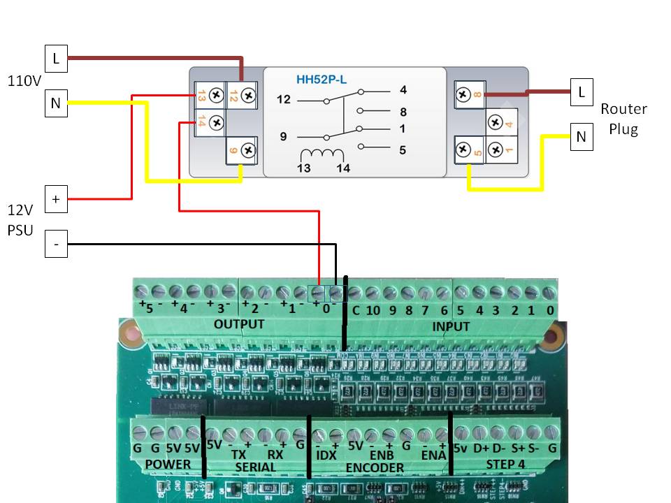
And when I configure via PNCCONF I would use Output 0 to be Spindle Enable?
I am heading down the wrong path here?
Currently I have a plug wired to receive power using the following;
www.amazon.com/dp/B07QXXM1RV/ref=cm_sw_e..._encoding=UTF8&psc=1
I am envisioning the wiring from my 7i96 to look like the following;
And when I configure via PNCCONF I would use Output 0 to be Spindle Enable?
I am heading down the wrong path here?
Attachments:
Please Log in or Create an account to join the conversation.
- PCW
-

- Offline
- Moderator
-

Less
More
- Posts: 17931
- Thank you received: 5255
27 Jan 2021 21:08 #196813
by PCW
Replied by PCW on topic Using 7i96 to Switch 110V Relay for Palm Router
You should have a flyback diode across the relay coil
Diode cathode = band to relay pin 13=+12V
In addition you should have a RC snubber circuit or varistor
across the relay contacts to prevent arcing which damages
the contacts and generate a lot of EMI.
Diode cathode = band to relay pin 13=+12V
In addition you should have a RC snubber circuit or varistor
across the relay contacts to prevent arcing which damages
the contacts and generate a lot of EMI.
Please Log in or Create an account to join the conversation.
- kotlikm
- Offline
- Junior Member
-
Less
More
- Posts: 21
- Thank you received: 0
27 Jan 2021 21:17 #196815
by kotlikm
Replied by kotlikm on topic Using 7i96 to Switch 110V Relay for Palm Router
Is that the same if I utilize a SSR instead of an EMR?
Please Log in or Create an account to join the conversation.
- hermann1976
-
- Offline
- Senior Member
-

Less
More
- Posts: 61
- Thank you received: 13
27 Jan 2021 21:38 #196828
by hermann1976
Replied by hermann1976 on topic Using 7i96 to Switch 110V Relay for Palm Router
From the Mesa descripton:
ISOLATED OUTPUT CHARACTERISTICS
The 6 isolated outputs use full floating MOSFET switches ( a DC Solid State Relay
or SSR ) and can be used just like a switch or relay contact. Maximum voltage is 36 VDC
and maximum load current is 2A. Inductive loads must have a flyback diode. The output
polarity must be observed (reversed outputs will be stuck-on).
Note: The 7I96 outputs are not short circuit protected so a current limited power
supply or a 2A to 5A fuse should be used in the power source that supplies the
outputs.
Maybe you should add a diode.
Please Log in or Create an account to join the conversation.
- PCW
-
- Offline
- Moderator
-
Less
More
- Posts: 17931
- Thank you received: 5255
27 Jan 2021 21:38 #196829
by PCW
Replied by PCW on topic Using 7i96 to Switch 110V Relay for Palm Router
No, typically you don't need any external components with a AC SSR
The following user(s) said Thank You: chrisfairbrothern
Please Log in or Create an account to join the conversation.
- andypugh
-

- Offline
- Moderator
-
Less
More
- Posts: 19863
- Thank you received: 4636
27 Jan 2021 23:46 - 27 Jan 2021 23:48 #196853
by andypugh
Replied by andypugh on topic Using 7i96 to Switch 110V Relay for Palm Router
I think an SSR would be my first choice. But the relay boards on Amazon advertised as for Arduino would work too, they generally have optical isolation.
That said, the Mesa card is completely capable of driving the relays directly, there just needs to be a protection diode.
_some_ relays have these fitted already.
(The ones you have show a diode symbol, but that is an LED so won't work. Apart from anything else it points the wrong way)
That said, the Mesa card is completely capable of driving the relays directly, there just needs to be a protection diode.
_some_ relays have these fitted already.
(The ones you have show a diode symbol, but that is an LED so won't work. Apart from anything else it points the wrong way)
Last edit: 27 Jan 2021 23:48 by andypugh.
Please Log in or Create an account to join the conversation.
- sprintertrd
- Offline
- Junior Member
-
Less
More
- Posts: 28
- Thank you received: 7
27 Jan 2021 23:53 #196855
by sprintertrd
Replied by sprintertrd on topic Using 7i96 to Switch 110V Relay for Palm Router
I would also wire the 110V ac the other way around. I would use pins 5 & 8 as the input 110V and 12 & 9 as the output. Doing it the way you have drawn pin 4 will be live (110V AC) whenever the spindle is not on
The following user(s) said Thank You: kotlikm
Please Log in or Create an account to join the conversation.
- kotlikm
- Offline
- Junior Member
-
Less
More
- Posts: 21
- Thank you received: 0
28 Jan 2021 00:29 #196864
by kotlikm
Replied by kotlikm on topic Using 7i96 to Switch 110V Relay for Palm Router
Thanks, after digging a bit more I agree on going SSR, looking at the following;
www.amazon.com/dp/B00E1LC1VK/ref=cm_sw_r...a_fabc_fvGeGbPJZMVV4
www.amazon.com/dp/B00E1LC1VK/ref=cm_sw_r...a_fabc_fvGeGbPJZMVV4
Please Log in or Create an account to join the conversation.
- kotlikm
- Offline
- Junior Member
-
Less
More
- Posts: 21
- Thank you received: 0
28 Jan 2021 02:07 #196876
by kotlikm
Replied by kotlikm on topic Using 7i96 to Switch 110V Relay for Palm Router
So I have my spindle enable mapped to my output 0, verified in my .hal and everything. I would expect to see continuity across 0+ and 0- output pins when I run an M3 S10000 command, but I get nothing.
Please Log in or Create an account to join the conversation.
- PCW
-
- Offline
- Moderator
-
Less
More
- Posts: 17931
- Thank you received: 5255
28 Jan 2021 04:41 #196893
by PCW
Replied by PCW on topic Using 7i96 to Switch 110V Relay for Palm Router
Could you post your hal file here?
Please Log in or Create an account to join the conversation.
Moderators: PCW, jmelson
Time to create page: 0.119 seconds