7i76ED to servo spindle - connection question
- spumco
- Offline
- Platinum Member
-

Less
More
- Posts: 2120
- Thank you received: 880
15 Feb 2021 04:45 #198898
by spumco
7i76ED to servo spindle - connection question was created by spumco
I've jumped in and am trying LinuxCNC for the first time. 7i76ED arrived and I'm working on the wiring diagram.
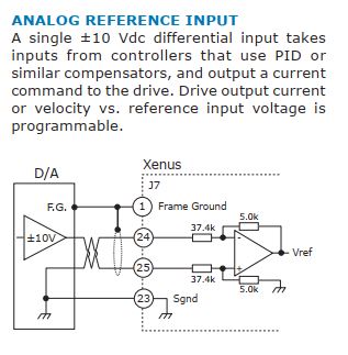
First stumbling point is analog spindle control. My spindle drive is a Copley Xenus XSL servo drive, and it's capable of multiple command input types (see attachment).
I'd prefer to use a standard 0-10V scheme, but I'm confused by the Copley +/-10V analog input diagram.
My previous experience is with VFD's that supply the Vref to a pot (or controller), and the Vsignal and V- return to the VFD. The 7i76ED appears to be set up to use the 'standard' VFD arrangement.
I suppose I could sacrifice an axis and use PWM command, but I'd rather not as I have plans for the 7i76ED's 5th S&D output.
Unless one of the other digital outputs can be used as a PWM?
If anyone can take a look at the Copley diagram and give me some guidance I'd appreciate it.
Thanks,
Ralph
Please Log in or Create an account to join the conversation.
- aleksamc
-

- Offline
- Platinum Member
-
Less
More
- Posts: 569
- Thank you received: 67
15 Feb 2021 21:51 #198990
by aleksamc
Replied by aleksamc on topic 7i76ED to servo spindle - connection question
I've worked with 7i76 few years ago. But I remember that there is 3 input pins (read manual) where you connect 10V, gnd and analog output. They work as potentiometer.
As for negative voltage to your FVD, many FVD has support of negative voltage but you set in settings how you want to negate direction: with analog or discreat input.
As for negative voltage to your FVD, many FVD has support of negative voltage but you set in settings how you want to negate direction: with analog or discreat input.
The following user(s) said Thank You: spumco
Please Log in or Create an account to join the conversation.
- spumco
- Offline
- Platinum Member
-
Less
More
- Posts: 2120
- Thank you received: 880
15 Feb 2021 22:56 #198997
by spumco
Replied by spumco on topic 7i76ED to servo spindle - connection question
Thanks, that confirms my understanding of the 7i76 analog connections.
But I'm still at a loss on the 'differential analog' input on the Copley drive.
Maybe supply 10v to the 7i76 Vin pin from a separate power supply, and the TB4 SPINDLE OUT & SPINDLE - get connected to Ref+ and Ref- on the drive?
But I'm still at a loss on the 'differential analog' input on the Copley drive.
Maybe supply 10v to the 7i76 Vin pin from a separate power supply, and the TB4 SPINDLE OUT & SPINDLE - get connected to Ref+ and Ref- on the drive?
Please Log in or Create an account to join the conversation.
- Michael
- Offline
- Platinum Member
-
Less
More
- Posts: 335
- Thank you received: 59
16 Feb 2021 02:34 - 16 Feb 2021 02:37 #199015
by Michael
Replied by Michael on topic 7i76ED to servo spindle - connection question
Look for a dc to dc converter that can output a + - voltage. I think they have them that do 24v to 12v. Bunch of other ranges as well but you will already have 24v nearby.
The + output will go to spindle+ and - to spindle-. Drive should connect to spindle out and the dc converter 0v pin (this may depend alot on which type you actually get. You can then scale the output voltage to whatever you like to be the max to come out of spindleout.
Also read through the drives analog section. A lot of them have a 0-10v option with a direction pin.
Last edit: 16 Feb 2021 02:37 by Michael.
The following user(s) said Thank You: spumco
Please Log in or Create an account to join the conversation.
- PCW
-

- Offline
- Moderator
-

Less
More
- Posts: 17936
- Thank you received: 5255
16 Feb 2021 02:41 #199016
by PCW
Replied by PCW on topic 7i76ED to servo spindle - connection question
If you are just running the spindle in velocity mode (no positioning)
you could reverse the spindle drive inputs with a DPDT relay
Note that the 7I76ED analog output is not suitable for position control
loops (too slow) and has a maximum voltage rating of 15V from SPIN- to SPIN+
you could reverse the spindle drive inputs with a DPDT relay
Note that the 7I76ED analog output is not suitable for position control
loops (too slow) and has a maximum voltage rating of 15V from SPIN- to SPIN+
Please Log in or Create an account to join the conversation.
- Michael
- Offline
- Platinum Member
-
Less
More
- Posts: 335
- Thank you received: 59
16 Feb 2021 02:44 #199017
by Michael
Replied by Michael on topic 7i76ED to servo spindle - connection question
Total voltage range is only 15v so you wouldn't be able to do +10 and -10?
Please Log in or Create an account to join the conversation.
- spumco
- Offline
- Platinum Member
-
Less
More
- Posts: 2120
- Thank you received: 880
16 Feb 2021 03:31 - 16 Feb 2021 03:32 #199019
by spumco
Replied by spumco on topic 7i76ED to servo spindle - connection question
Thanks all.
I'm only interested in velocity mode, so that part's sorted.
Re-reading the drive manual, it looks like it can accept a 0-10v input, and I could use the scaling and offset functions in the drive to adjust the desired range. So a 5v signal would be stopped, and 0v would be CCW. Start/stop would be digital input enable signal.
Correct me if I'm wrong...
1. SPINDLE+ connected to power supply V+ (adjusted to 10v)
2. SPINDLE- connected to power supply V-
3. SPINDLE OUT to drive Ref+
4. SPINDLE- also to drive Ref- (or to PS V-, same thing)
Is the 0-10v CW/CCW scheme possible in LCNC? I don't see that a direction command is possible on one of the GP digital inputs.
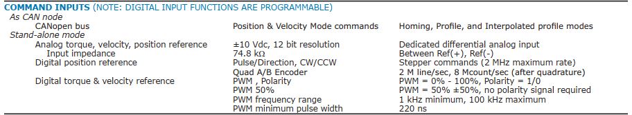
Snippet from manual:

I'm only interested in velocity mode, so that part's sorted.
Re-reading the drive manual, it looks like it can accept a 0-10v input, and I could use the scaling and offset functions in the drive to adjust the desired range. So a 5v signal would be stopped, and 0v would be CCW. Start/stop would be digital input enable signal.
Correct me if I'm wrong...
1. SPINDLE+ connected to power supply V+ (adjusted to 10v)
2. SPINDLE- connected to power supply V-
3. SPINDLE OUT to drive Ref+
4. SPINDLE- also to drive Ref- (or to PS V-, same thing)
Is the 0-10v CW/CCW scheme possible in LCNC? I don't see that a direction command is possible on one of the GP digital inputs.
Snippet from manual:
Last edit: 16 Feb 2021 03:32 by spumco.
Please Log in or Create an account to join the conversation.
- aleksamc
-
- Offline
- Platinum Member
-
Less
More
- Posts: 569
- Thank you received: 67
16 Feb 2021 05:20 #199025
by aleksamc
Replied by aleksamc on topic 7i76ED to servo spindle - connection question
You need to use in HAL
halui.spindle.0.runs−backward
it's output signal and you should connect it to servo direction input
halui.spindle.0.runs−backward
it's output signal and you should connect it to servo direction input
Please Log in or Create an account to join the conversation.
- spumco
- Offline
- Platinum Member
-
Less
More
- Posts: 2120
- Thank you received: 880
16 Feb 2021 14:34 #199065
by spumco
Replied by spumco on topic 7i76ED to servo spindle - connection question
The drive only accepts direction input in PWM (torque, velocity, position) or S&D modes.
In any of the analog modes it either uses +/-10v for CW/CCW, or 0-10v with the appropriate offset (0-5v is CCW, 5-10v is CW).
I'm beginning to think going with PWM might be simpler. I can always add a 7i85 to get back an additional axis.
Do I need to flash or otherwise configure the 7i76ED for PWM output on TB3 STEP4?
Please Log in or Create an account to join the conversation.
- aleksamc
-
- Offline
- Platinum Member
-
Less
More
- Posts: 569
- Thank you received: 67
16 Feb 2021 15:37 #199073
by aleksamc
Replied by aleksamc on topic 7i76ED to servo spindle - connection question
If servo doesn't support change of direction with discreet input, than you can use relay that will change polarity of your output.
Or you may buy additional board.
Or you may buy additional board.
Please Log in or Create an account to join the conversation.
Moderators: PCW, jmelson
Time to create page: 0.145 seconds