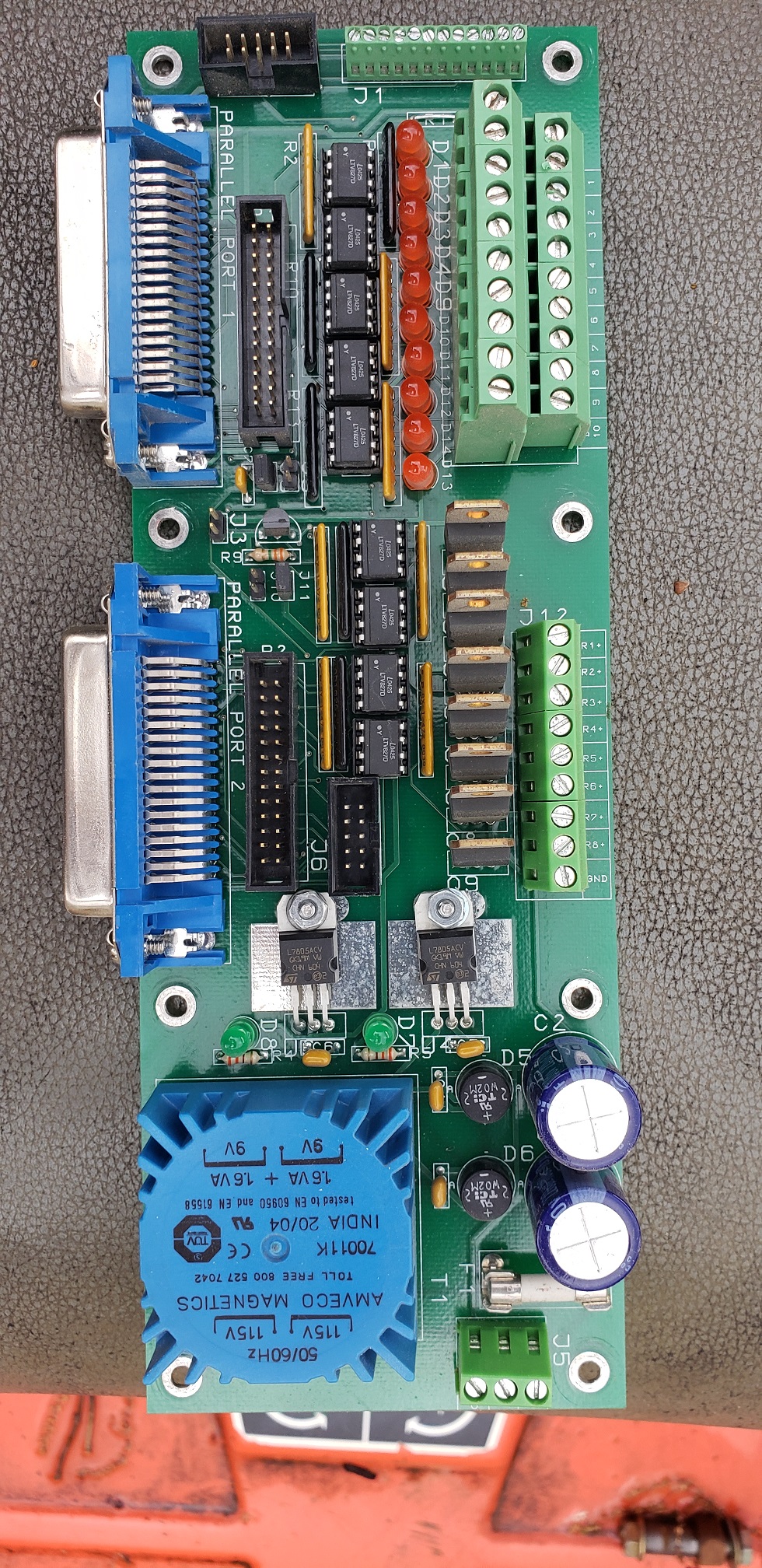
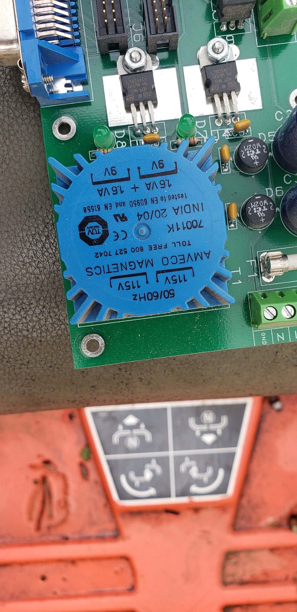
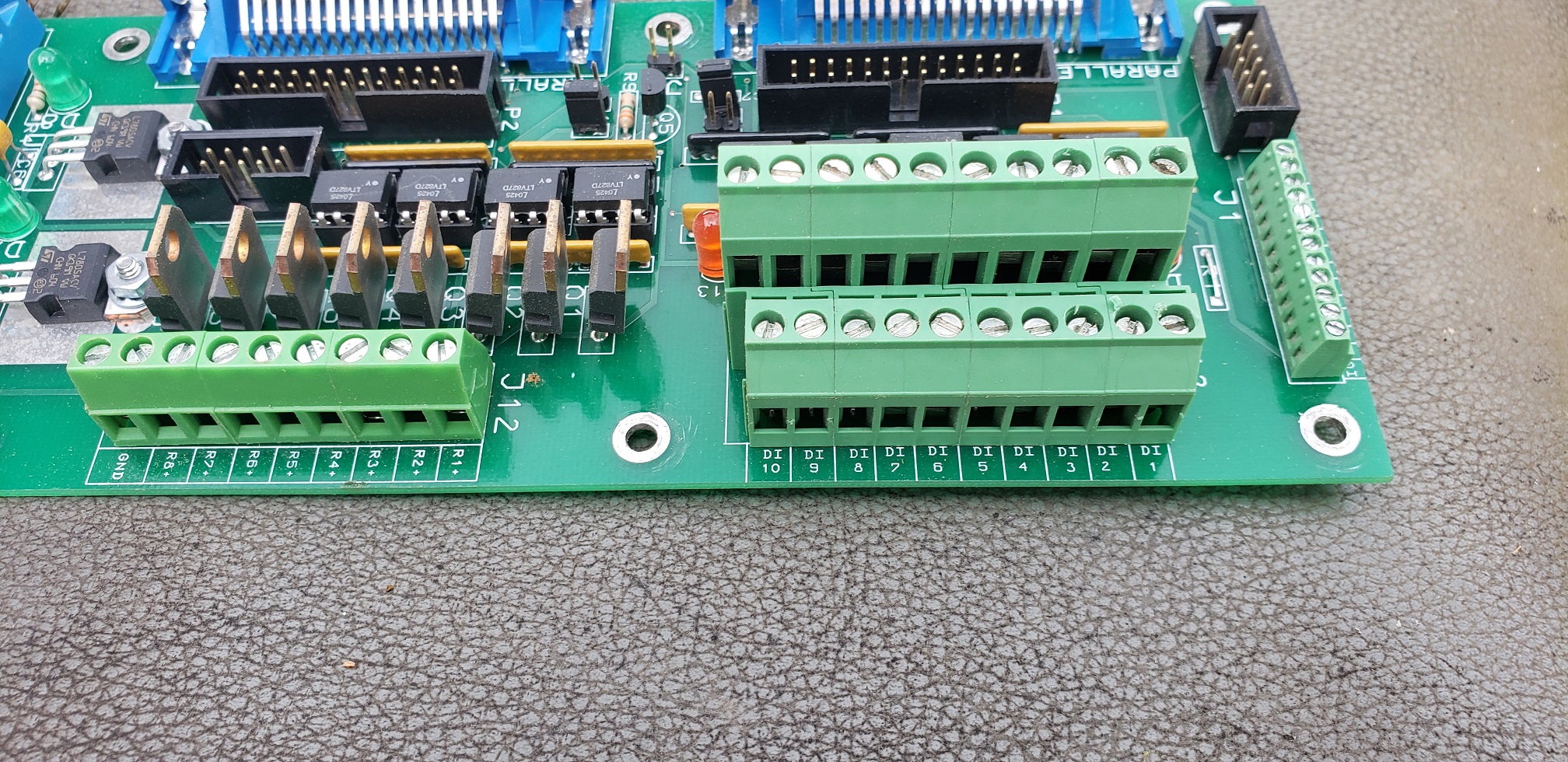
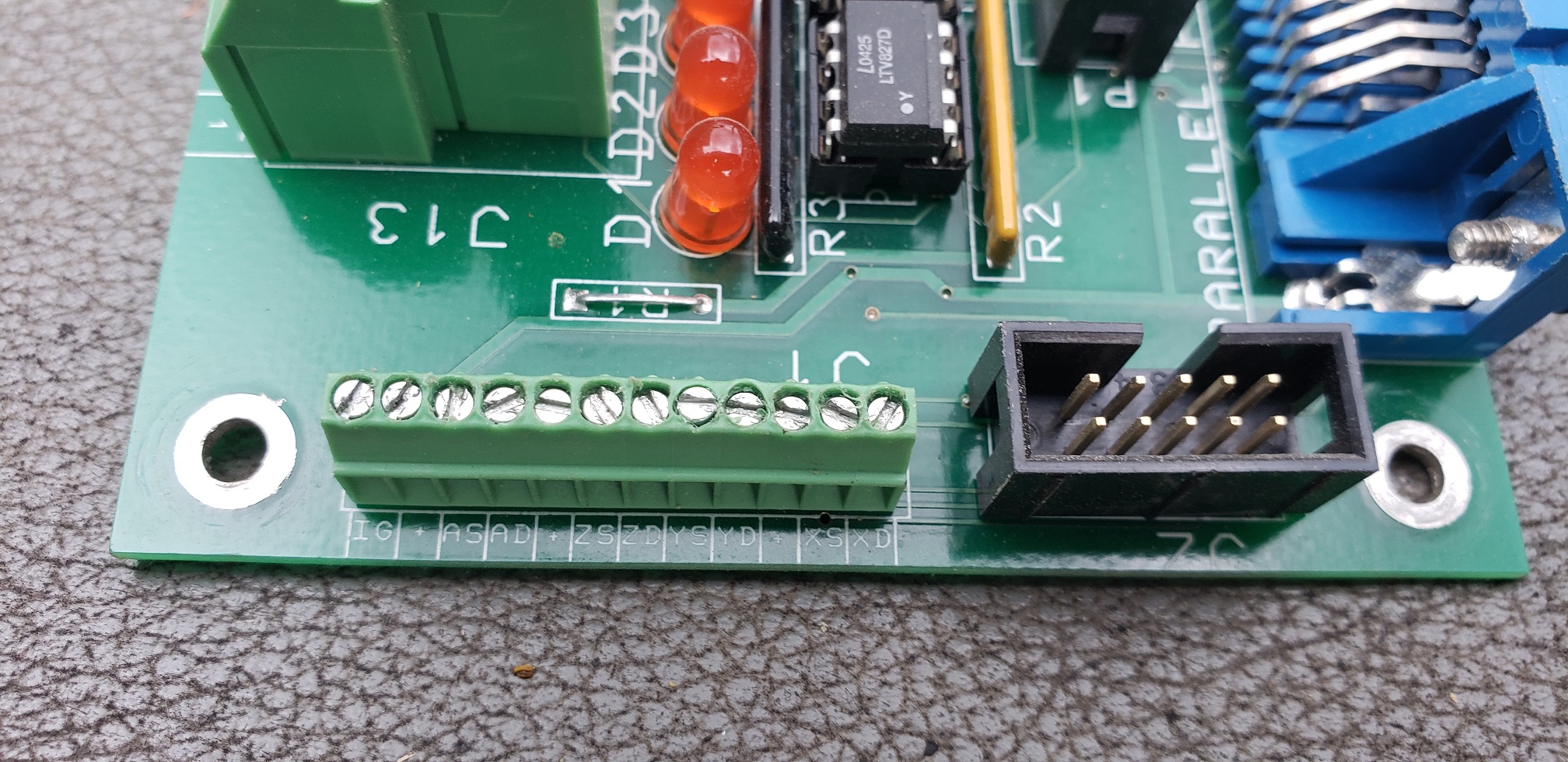
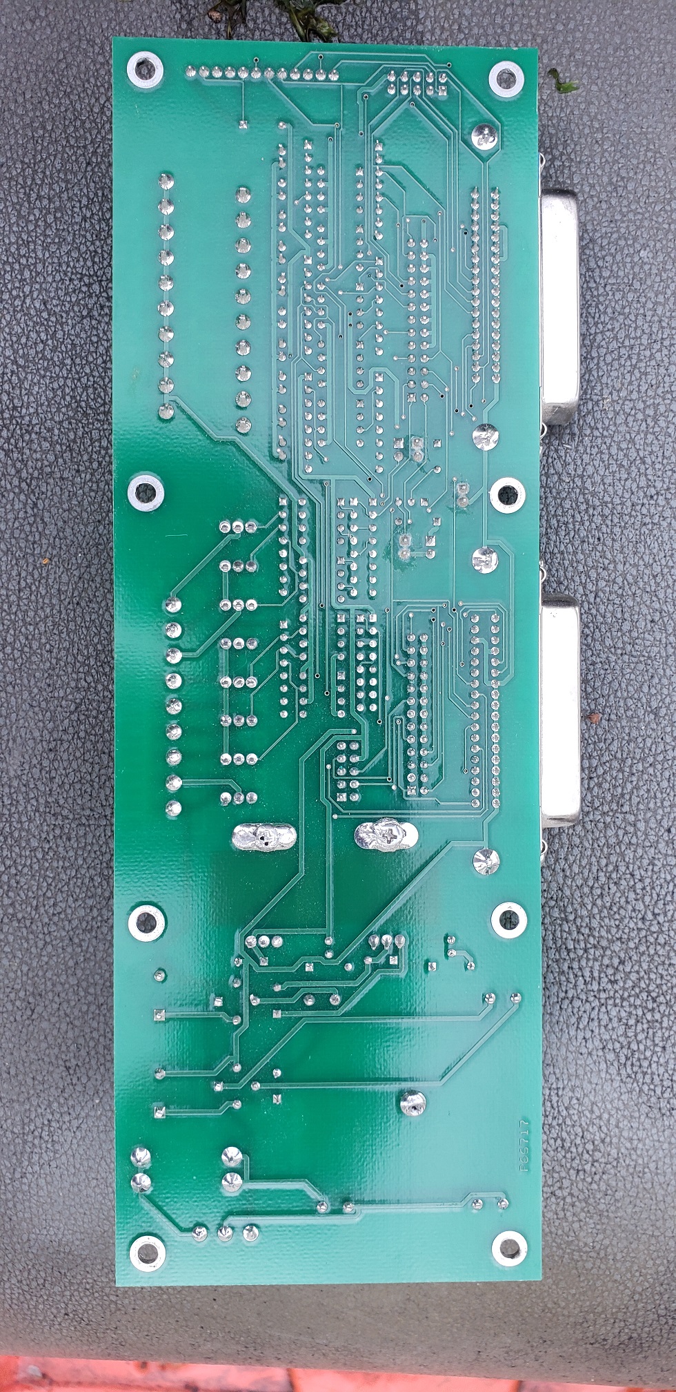
Old Breakout Board trying to identify
- GMC
- Offline
- New Member
-

Less
More
- Posts: 2
- Thank you received: 0
04 May 2022 19:02 #241993
by GMC
Old Breakout Board trying to identify was created by GMC
Need a little help. Bought a used CNC Router with Mach3. Do not know what model or make of the Breakout/Controller boards is. It works fine for controlling the stepper motors and has inputs for limit switches and E-stop. Except the inputs are not being seen by Mach 3 or Linuxcnc. The led's come on when the switches close but no indication ion Mach 3. I hope someone out there can help me for the make and model of this board. In the mean time I bought a cheap breakout board to get the machine running correctly. I Hope.
Attachments:
Please Log in or Create an account to join the conversation.
- tommylight
-

- Away
- Moderator
-

Less
More
- Posts: 21225
- Thank you received: 7246
04 May 2022 19:49 #241997
by tommylight
Replied by tommylight on topic Old Breakout Board trying to identify
Pictures of the underside?
Please Log in or Create an account to join the conversation.
- andypugh
-

- Offline
- Moderator
-

Less
More
- Posts: 19789
- Thank you received: 4605
04 May 2022 20:59 #242004
by andypugh
Replied by andypugh on topic Old Breakout Board trying to identify
It looks to need a mains voltage supply, is it getting one?
Please Log in or Create an account to join the conversation.
- robertspark
- Offline
- Platinum Member
-

Less
More
- Posts: 915
- Thank you received: 216
04 May 2022 22:02 - 04 May 2022 22:04 #242011
by robertspark
Replied by robertspark on topic Old Breakout Board trying to identify
I had a look for the board as its not one I recognise in ~10 years I've been involved with cnc and did not find anything.
Given the voltage rating it will be a US only market board. Looking at the board detail its not something I've seen from any other manfacturer (board makers like cnc4pc, or PDMX, warp9, texas microcircuits etc all tend to use a similar pattern / style in their board design... you see similar components repeated / connectors etc even if they make or design boards for someone else).
I am guessing that your problem will be the jumpers in the centre of the board. I am guessing that these may provide 5v to the DIP optoisolators. you may need to study the board a bit. you'll see that the jumper for the output is set differently to the inputs side of the board.
Sometimes 5V is provided from pin 26 of the IDC connector (the black rectangular one in front of the LPT blue connector) and that jumper could be to switch from board 5v to the IDC connector supplied 5v.
I'd suggest not changing anything until you study the board.
You may need to get a volt meter out to measure the voltages around those jumpers to see what the difference is between the two jumper settings.
A rear view of the board will help as Tommy asked earlier.
Last edit: 04 May 2022 22:04 by robertspark.
The following user(s) said Thank You: tommylight
Please Log in or Create an account to join the conversation.
- tommylight
-

- Away
- Moderator
-

Less
More
- Posts: 21225
- Thank you received: 7246
04 May 2022 22:14 #242013
by tommylight
 ), it has 2 primary winding so it can be used in US and EU, in US wired in parallel, in EU wired in series.
That type of transformers is "old school" now so rarely seen, unfortunately i have a full rack of them from 200W to 800W collecting dust as SMPS rendered them useless, and heavy, and vibraty-noisy, and.... never mind !
Replied by tommylight on topic Old Breakout Board trying to identify
If you are referring to the 115V written on the transformer (blue "sun" looking thingyGiven the voltage rating it will be a US only market board.
That type of transformers is "old school" now so rarely seen, unfortunately i have a full rack of them from 200W to 800W collecting dust as SMPS rendered them useless, and heavy, and vibraty-noisy, and.... never mind !
The following user(s) said Thank You: GMC
Please Log in or Create an account to join the conversation.
- GMC
- Offline
- New Member
-

Less
More
- Posts: 2
- Thank you received: 0
05 May 2022 13:11 #242038
by GMC
Replied by GMC on topic Old Breakout Board trying to identify
Attachments:
Please Log in or Create an account to join the conversation.
- andypugh
-

- Offline
- Moderator
-

Less
More
- Posts: 19789
- Thank you received: 4605
05 May 2022 14:40 #242043
by andypugh
Replied by andypugh on topic Old Breakout Board trying to identify
Have you checked the fuse?
Please Log in or Create an account to join the conversation.
- robertspark
- Offline
- Platinum Member
-

Less
More
- Posts: 915
- Thank you received: 216
05 May 2022 16:00 #242047
by robertspark
Replied by robertspark on topic Old Breakout Board trying to identify
not a lot of use the bottom image is other than being able to trace out the tracks....
I suspected that it used the Centronics Connector, but wasn't sure until now
karusisemus.files.wordpress.com/2016/07/centronics.png
Tommy pointed out something I was not aware of using the centre tap 115V transformer for 230v (I am aware it's done + how to do it.... just was not aware it was so common).
However looking at the rear traces it's set for 115V input voltage, so likely to be US market manufactured (or japan? {unlikely but I think they run on 100v})
I am out of ideas.
I was looking at tracing the jumpers out but it's probably best done with a volt meter.
The following user(s) said Thank You: tommylight, GMC
Please Log in or Create an account to join the conversation.
- tommylight
-

- Away
- Moderator
-

Less
More
- Posts: 21225
- Thank you received: 7246
05 May 2022 21:06 #242068
by tommylight
That seems correct.
Replied by tommylight on topic Old Breakout Board trying to identify
However looking at the rear traces it's set for 115V input voltage, so likely to be US market manufactured (or japan? {unlikely but I think they run on 100v})
That seems correct.
The following user(s) said Thank You: GMC
Please Log in or Create an account to join the conversation.
Moderators: PCW, jmelson
Time to create page: 0.196 seconds

