My 7i76 wiring plan for JMC iHSV57 servos and peripherals
- knipknap
- Offline
- Premium Member
-

Less
More
- Posts: 96
- Thank you received: 6
16 Dec 2022 12:48 - 16 Dec 2022 18:30 #259632
by knipknap
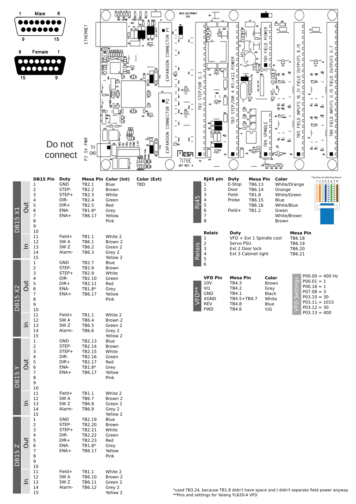
So this is my wiring plan for a dual independent X-Axis CNC using JMC HSV57 servos, as well as the wiring for the YL620-A VFD.
Anything obvious that I forgot? Did I forget any must-have peripherals/inputs?
(Not pictured: 42V servo power is wired separately.)
My 7i76 wiring plan for JMC iHSV57 servos and peripherals was created by knipknap
So this is my wiring plan for a dual independent X-Axis CNC using JMC HSV57 servos, as well as the wiring for the YL620-A VFD.
Anything obvious that I forgot? Did I forget any must-have peripherals/inputs?
(Not pictured: 42V servo power is wired separately.)
Attachments:
Last edit: 16 Dec 2022 18:30 by knipknap.
Please Log in or Create an account to join the conversation.
- andypugh
-

- Offline
- Moderator
-

Less
More
- Posts: 19879
- Thank you received: 4643
17 Dec 2022 23:55 #259787
by andypugh
Replied by andypugh on topic My 7i76 wiring plan for JMC iHSV57 servos and peripherals
Without looking at the drive manuals (which I don't really have time to do) it isn't easy to say whether what you have is correct.
Be aware that unless TB1 has field power connected then the smart-serial subsystem will be unpowered and you will not see your GPIO.
if the polarities are all correct then worst case is that it won't work and you can ask us specific questions.
Be aware that unless TB1 has field power connected then the smart-serial subsystem will be unpowered and you will not see your GPIO.
if the polarities are all correct then worst case is that it won't work and you can ask us specific questions.
Please Log in or Create an account to join the conversation.
- knipknap
- Offline
- Premium Member
-
Less
More
- Posts: 96
- Thank you received: 6
18 Dec 2022 11:43 - 18 Dec 2022 11:44 #259815
by knipknap
Replied by knipknap on topic My 7i76 wiring plan for JMC iHSV57 servos and peripherals
Thank you! Of course, checking every pin would be too much work, I was more worried about whether I have taken all the right pins into consideration or forgot any major parts. More specifically:
- Since the X axis uses dual independent motors (and end switches), do I need to wire the PED+ and - from the servo driver? Or do I have to take anything else into consideration?
- In addition to E-Stop, Door sensor, and Probe inputs, did I forget any must-have peripherals?
- Is it ok to use a relais to turn on/off servo power, or could that lead to problems?
- ...?
In other words, I am more worried about the general completeness of my plan, rather than the individual pinout.
Last edit: 18 Dec 2022 11:44 by knipknap.
Please Log in or Create an account to join the conversation.
- andypugh
-
- Offline
- Moderator
-
Less
More
- Posts: 19879
- Thank you received: 4643
19 Dec 2022 23:16 - 19 Dec 2022 23:18 #259908
by andypugh
Replied by andypugh on topic My 7i76 wiring plan for JMC iHSV57 servos and peripherals
Never have any relay between the servo drive / VFD / stepper driver and the motor. Other than that it is probably fine to turn on/off servo drives with a relay. It's easier to switch on the AC side, rather than breaking the DC supply (depending on the servo drive they may take AC input, or DC input from a separate PSU)
If you need to break DC then make sure the relays are rated for it.
I don't see PED+ and - on the pinout diagram. What are they?
If you need to break DC then make sure the relays are rated for it.
I don't see PED+ and - on the pinout diagram. What are they?
Last edit: 19 Dec 2022 23:18 by andypugh.
Please Log in or Create an account to join the conversation.
- knipknap
- Offline
- Premium Member
-
Less
More
- Posts: 96
- Thank you received: 6
20 Dec 2022 17:35 #259971
by knipknap
Replied by knipknap on topic My 7i76 wiring plan for JMC iHSV57 servos and peripherals
Ok, I made sure not to switch DC anywhere using a relay.
PED+ and - are on the servo drivers. I think they are meant to signal back to the controller when the servo has reached a specific position. So far I have not connected them anywhere though, which is why they don't show in the plan. But I am not sure if they are required for synchronizing both X axis servos.
PED+ and - are on the servo drivers. I think they are meant to signal back to the controller when the servo has reached a specific position. So far I have not connected them anywhere though, which is why they don't show in the plan. But I am not sure if they are required for synchronizing both X axis servos.
Please Log in or Create an account to join the conversation.
- andypugh
-
- Offline
- Moderator
-
Less
More
- Posts: 19879
- Thank you received: 4643
21 Dec 2022 01:08 #259988
by andypugh
Replied by andypugh on topic My 7i76 wiring plan for JMC iHSV57 servos and peripherals
You probably want to take limit switches to LinuxCNC rather than to the drives. The drives don't need to know.
Please Log in or Create an account to join the conversation.
- knipknap
- Offline
- Premium Member
-
Less
More
- Posts: 96
- Thank you received: 6
21 Dec 2022 11:12 #259999
by knipknap
Replied by knipknap on topic My 7i76 wiring plan for JMC iHSV57 servos and peripherals
My understanding of PED is different, I think it is supposed to signal when all motion instructions that were sent to the driver have been successfully executed. It doesn't signal absolute positions like limit switches would.
So it could be used to synchronize multiple motors. But I am not sure that my understanding is correct.
So it could be used to synchronize multiple motors. But I am not sure that my understanding is correct.
Please Log in or Create an account to join the conversation.
Moderators: PCW, jmelson
Time to create page: 0.138 seconds