Output Mesa 7i96s - Struggle making it work
- Odinos42
- Offline
- New Member
-

Less
More
- Posts: 3
- Thank you received: 0
26 Jun 2023 12:36 #274244
by Odinos42
Output Mesa 7i96s - Struggle making it work was created by Odinos42
Hey,
I'm trying to control a 12volt DC solenoid valve with the output of the 7i96s.
For testing, in Pnnconf I have configured the OUTPUT SSR 01 in the TB3 Tab, as a Spindle. In axis, when I clic on the spindle+ button i can see the LED of the mesa card output ON, but it's seems no current is passing throught it when I'm measuring with a multimeter.
Right now my setup is like that:
PSU + >> Fuse 5A >> MOSFET VIN+
PSU - >> MOSFET VIN -
MOSFET OUTPUT + >> FLYBACK DIOD CATHODE >> MOSFET OUTPUT- >> FLYBACK DIOD ANODE
MOSFET OUTPUT + >> SOLENOID VALVE +
MOSFET OUTPUT - >> SOLENOID VALVE -
MESA OUTPUT + >> MOSFET TRIGGER
MESA OUTPUT - >> MOSFET GND >> PSU GROUND
I'm struggling since I'm really a newbie, thanks for your help!
Please Log in or Create an account to join the conversation.
- tommylight
-

- Offline
- Moderator
-

Less
More
- Posts: 21686
- Thank you received: 7411
26 Jun 2023 13:05 #274245
by tommylight
Replied by tommylight on topic Output Mesa 7i96s - Struggle making it work
NPN mosfets require voltage to gate, you have it tied to 0V/GND.
Also, MOSFET's do need a pull down resistor on the gate, otherwise it remains open.
PNP MOSFET's require pullup resistor to gate.
And they are quite limited on gate voltage, 5V is not enough for most of them to open properly, except for TTL level ones, and the upper limit is 15 to 20V.
Using a transistor (bipolar or darlington) is easier and less fuss, just add a resistor in series with the base.
Please Log in or Create an account to join the conversation.
- Odinos42
- Offline
- New Member
-
Less
More
- Posts: 3
- Thank you received: 0
26 Jun 2023 13:25 #274248
by Odinos42
Replied by Odinos42 on topic Output Mesa 7i96s - Struggle making it work
Ok! Thx for this input.
Is it normal to see the LED ON of the corresponding output but not being able to measure any current from the pins (I'm scared to have damaged the card, even if the stepper and limits are still working).
If I have to sumup, this will be my new setup :
Power Supply to Transistor:
PSU (+) terminal to the Collector (C) of the transistor.
PSU's (-) terminal to the Emitter (E) of the transistor. (For a Darlington transistor, this would be the Collector of T2 and the Emitter of T1).
Transistor to Solenoid Valve:
Emitter (E) of the transistor to the "-" terminal of the solenoid valve.
The "+" terminal of the solenoid valve directly to the PSU's positive (+) terminal.
Flyback Diode:
Flyback diode across the solenoid valve terminals, observing correct polarity. The anode connect to the solenoid's negative terminal, and the cathode connect to the solenoid's positive terminal.
Mesa Card to Transistor:
Output's "+" terminal to a suitable base resistor (e.g., 1k ohm), and the other end of the resistor to the Base (") of the transistor.
of the transistor.
Output's "-" terminal should connect to the PSU's negative (-) terminal (GND).
Fuse: a 2A fuse between the power supply and the solenoid valve.
Is this correct ?
Is it normal to see the LED ON of the corresponding output but not being able to measure any current from the pins (I'm scared to have damaged the card, even if the stepper and limits are still working).
If I have to sumup, this will be my new setup :
Power Supply to Transistor:
PSU (+) terminal to the Collector (C) of the transistor.
PSU's (-) terminal to the Emitter (E) of the transistor. (For a Darlington transistor, this would be the Collector of T2 and the Emitter of T1).
Transistor to Solenoid Valve:
Emitter (E) of the transistor to the "-" terminal of the solenoid valve.
The "+" terminal of the solenoid valve directly to the PSU's positive (+) terminal.
Flyback Diode:
Flyback diode across the solenoid valve terminals, observing correct polarity. The anode connect to the solenoid's negative terminal, and the cathode connect to the solenoid's positive terminal.
Mesa Card to Transistor:
Output's "+" terminal to a suitable base resistor (e.g., 1k ohm), and the other end of the resistor to the Base (
of the transistor.Output's "-" terminal should connect to the PSU's negative (-) terminal (GND).
Fuse: a 2A fuse between the power supply and the solenoid valve.
Is this correct ?
Please Log in or Create an account to join the conversation.
- tommylight
-
- Offline
- Moderator
-
Less
More
- Posts: 21686
- Thank you received: 7411
26 Jun 2023 13:35 #274250
by tommylight
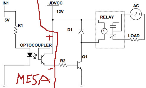
Replied by tommylight on topic Output Mesa 7i96s - Struggle making it work
Attachments:
Please Log in or Create an account to join the conversation.
- PCW
-

- Offline
- Moderator
-
Less
More
- Posts: 17946
- Thank you received: 5257
26 Jun 2023 23:14 - 26 Jun 2023 23:19 #274287
by PCW
Replied by PCW on topic Output Mesa 7i96s - Struggle making it work
What is the rating of the solenoid valve?
Can you not drive it directly?
Direct connection would be:
+12V --> 2A fuse -->7I96OUT1+
7I96OUT1- --> Solenoid+ and Flyback diode cathode
Solenoid- and Flyback diode anode --> 12V common
If you are driving a MOSFET with the 7I96/7I96S SSR outputs
you would need a pull down resistor since the SSR outputs
are basically a SPST switch, so they can turn the MOSFET on
but there is no current path to discharge the MOSFET gate when
the SSR is off.
Last edit: 26 Jun 2023 23:19 by PCW.
Please Log in or Create an account to join the conversation.
- Odinos42
- Offline
- New Member
-
Less
More
- Posts: 3
- Thank you received: 0
27 Jun 2023 06:10 - 27 Jun 2023 06:26 #274296
by Odinos42
Replied by Odinos42 on topic Output Mesa 7i96s - Struggle making it work
This sound so simple now!! Its work with direct connection. Thanks for your simple and straight forward explanations.
Now when I click on spindle clockwise button in Axis i can Open the solenoid valve and close it with the stop button.
Its works thanks to this line in My hal file:
net spindle-enable => [HMOT](CARDO).ssr.00.out-00
My solenoid Valve is plug to a pneumatic cylinder (that will need to open and close really often during the process).
How can I control it with Mcode in my final Gcodes? I'm trying M3 or M4 (from Mcode documentation about spindle) but doesn't seems to work.
EDIT: I just find out that On manual control It need to be activate first with M48 ( "M48 - enable the spindle speed and feed rate override controls."), and then M3 to open and M5 to close. But its seems to work only in manual control. What is the good way of doing it ?
Last edit: 27 Jun 2023 06:26 by Odinos42.
Please Log in or Create an account to join the conversation.
- andypugh
-

- Offline
- Moderator
-
Less
More
- Posts: 19871
- Thank you received: 4640
01 Jul 2023 10:55 #274584
by andypugh
Replied by andypugh on topic Output Mesa 7i96s - Struggle making it work
Something odd here, it is not usual to need M48 to enable M3.
Do you _want_ to use the spindle to control the relay? There are many other ways to do it, if the relay isn't actually controlling a spindle.
Do you _want_ to use the spindle to control the relay? There are many other ways to do it, if the relay isn't actually controlling a spindle.
Please Log in or Create an account to join the conversation.
Moderators: PCW, jmelson
Time to create page: 0.165 seconds