- Hardware & Machines
- Driver Boards
- Mesa Board with high tolerance for high frequency with 24v Step-gen?
Mesa Board with high tolerance for high frequency with 24v Step-gen?
- santy
- Offline
- Premium Member
-

- Posts: 117
- Thank you received: 10
I am addind emi filters on every power supply, as only the motors had them until now.
Even the twisted wires for outputs i have used.
Is it better to add the 0.01uF condenser at the +5v and gnd at the 7i96s, or at the step+,step- and another at dir+,dir- ?
I have been testing on a test machine to run the step generators with condensers and 100 ohm resistances on every wire (lol), to check how the signal changes with an oscilloscope. what can i use to "simulate" interference in a harmless way and test improvements IRL?
thank you.
Please Log in or Create an account to join the conversation.
- PCW
-

- Offline
- Moderator
-

- Posts: 17940
- Thank you received: 5255
(at the 7I96S 6 pin connector ideally)
Please Log in or Create an account to join the conversation.
- blazini36
- Offline
- Platinum Member
-

- Posts: 972
- Thank you received: 167
Servo drives usually have optocoupled inputs so it sounds like the ICs on the Mesa card are blowing because of transient voltages getting into the cable....is that the common thought? I assume you have some inputs and outputs going from the same 7i96 into the samebox the servo drives are, but they are not failing? The outputs on the 7i96 have a magnetic isolator (looks similar to what's used on ethernet jacks) and maybe TVS diodes? The inputs are optocouplers, so what you're blowing is probably the only non-isolated outputs you have coming from the 7i96 to the box with the goodies.
All the suggestions in the thread are good but wouldn't it make sense to actually isolate the stepgen outputs? I've never had great luck selecting fast optocouplers, they're out there but for connecting UART to noisy servo drives I use ADuM1201's which are pretty fast magnetic isolators. You could use the step outputs as single-ended, you'd actually want something like an ADuM1200, and all the cheap little break outs sold are for 1201's and for the sake of a convenient add on to your current setup I would literally Take some ADuM1200 chips and solder them into the step cables, cover them with some kind of hot snot then heat shrink them. Of course it would be better to make a proper break out board and that's super low effort as well.
Beyond that what about sticking some TVS diodes between the stepgen outputs and ground?
Please Log in or Create an account to join the conversation.
- blazini36
- Offline
- Platinum Member
-
- Posts: 972
- Thank you received: 167
Any reason why this concept wouldn't solve the issue and still work for differential step outputs?
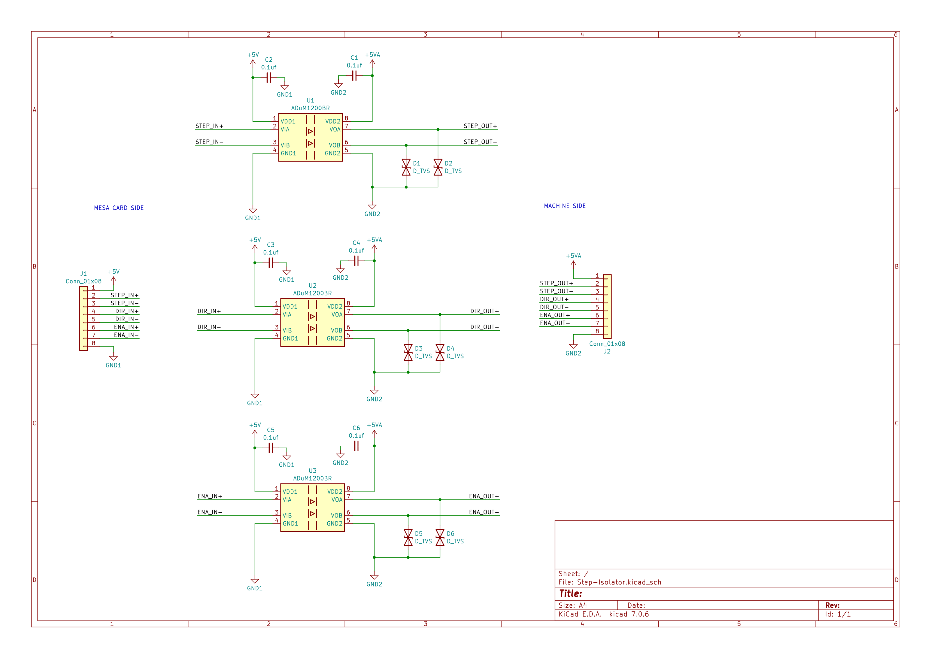
Edit: Just noticed the prices on the 1200's are out there for 2 channels.....ADuM160N is a 6channel device for $5 in small quantities. Still cheaper than killing Mesa cards.
Attachments:
Please Log in or Create an account to join the conversation.
- PCW
-
- Offline
- Moderator
-
- Posts: 17940
- Thank you received: 5255
by the 7I96S 5V and GND, the isolators will get damaged in the same way as the
driver chips on the 7I96S.
Please Log in or Create an account to join the conversation.
- blazini36
- Offline
- Platinum Member
-
- Posts: 972
- Thank you received: 167
Please Log in or Create an account to join the conversation.
- PCW
-
- Offline
- Moderator
-
- Posts: 17940
- Thank you received: 5255
I still think coupled transients large enough to damage the drivers
indicates a grounding/shielding issue that may cause additional
problems down the line.
Please Log in or Create an account to join the conversation.
- tommylight
-

- Offline
- Moderator
-
- Posts: 21683
- Thank you received: 7405
+1
I still think coupled transients large enough to damage the drivers
indicates a grounding/shielding issue that may cause additional
problems down the line.
Please Log in or Create an account to join the conversation.
- blazini36
- Offline
- Platinum Member
-
- Posts: 972
- Thank you received: 167
I don't disagree with that. I don't have a CNC plasma but it sounds like this is a difficult issue to resolve if it's jumping around between enclosures. The inputs and outputs of a 7i96 seem reasonably well isolated as you can isolate the IO supplies but you can't do that with the step outputs. This would at least resolve that would it not?Oh, OK I didn't zoom in on the schematic so missed that. I still think coupled transients large enough to damage the driversindicates a grounding/shielding issue that may cause additionalproblems down the line.
This is more of a response to sticking capacitors and stuff on everything. If there's a grounding/shielding issue, the caps aren't going to resolve that, they'll just snub some of the transients. I'm not saying that won't work, but it's less of a solution to a "grounding/shielding" issue than a digital isolator is. At least you can physically separate the problem electronics from the sensitive ones with isolators.
Attachments:
Please Log in or Create an account to join the conversation.
- santy
- Offline
- Premium Member
-
- Posts: 117
- Thank you received: 10
My question here is about the 5v on the Servo side.
My servos dont have a 5v output channel. Can i use a 5v Power supply to power the servo side of the 3 ADUM modules?
Please Log in or Create an account to join the conversation.
- Hardware & Machines
- Driver Boards
- Mesa Board with high tolerance for high frequency with 24v Step-gen?