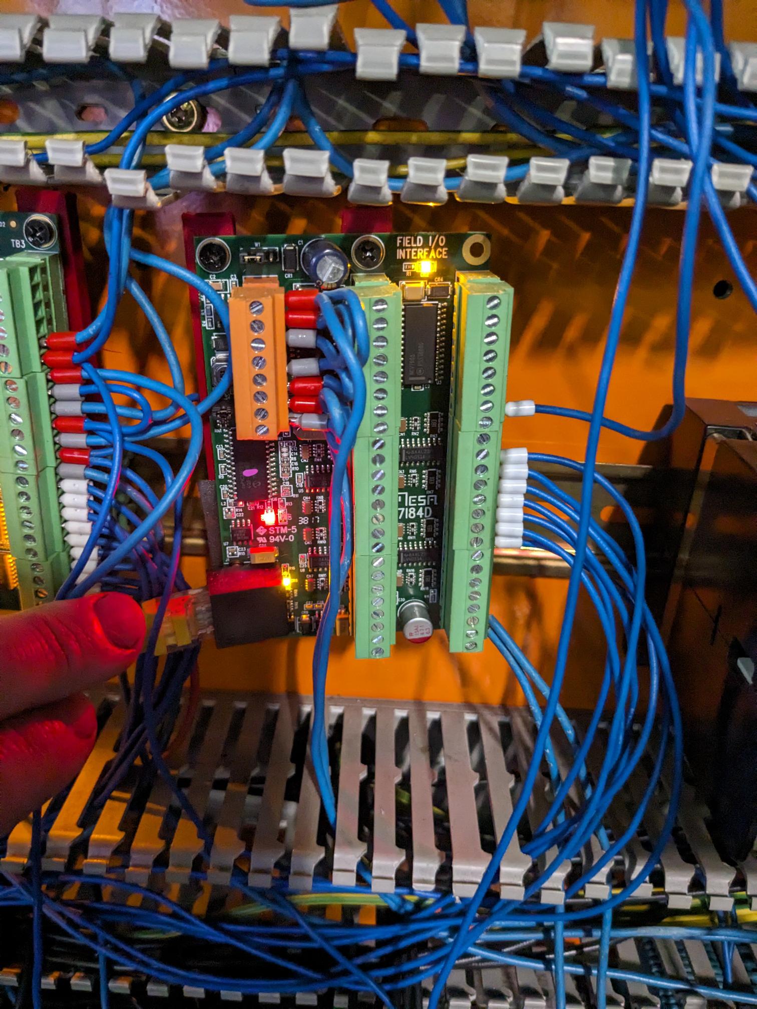
7i84 output wiring
- Walkahz
- Offline
- Junior Member
-

Less
More
- Posts: 38
- Thank you received: 7
06 May 2024 11:48 #299930
by Walkahz
7i84 output wiring was created by Walkahz
Hi
I am having some issues setting up my 7i84 connected to 7i96s .
i can't figure out the inputs and outputs on the 7i84.
The 7i96 is easy as it has 2 pins per IO
THe 7i84 having only the one from my understanding I need to ground or have set to 24v. Pending my card model.
I have got the tb1 pins set to 24v and have checked polarity.
I am trying to use the output to drive a relay. However when checking the output after it is activated on HAL I can't get it to function when tested with a multi meter. I have also tried connecting the other side of the relay to both ground and 24v and cannot get the relay to trigger.
For inputs they all measure at 24v
Any ideas? Or pointers for what I'm doing wrong?
Photo is of current connections.
Attachments:
Please Log in or Create an account to join the conversation.
- tommylight
-

- Online
- Moderator
-

Less
More
- Posts: 21227
- Thank you received: 7249
06 May 2024 12:24 #299932
by tommylight
Replied by tommylight on topic 7i84 output wiring
The card is not active at all as noted by the red LED, so check the wiring and check if it is being loaded.
To explain a bit in general
-sourcing output = means it gives out +5V or +12V or +24V depending on power supplied to it = the other load pin goes to 0V/GND
-sinking outputs = means they go to 0V/GND when active = the other load pin goes to +5/12/24V
Do read the manual, you have the 7i84D, not 7i84, they are the same functionally, but not the same wiring wise .
Please Log in or Create an account to join the conversation.
- Walkahz
- Offline
- Junior Member
-

Less
More
- Posts: 38
- Thank you received: 7
07 May 2024 00:25 #299983
by Walkahz
Replied by Walkahz on topic 7i84 output wiring
Thanks for the information.
The Red LED I was a bit suspect on so will need to do some looking into this could this potentially be a configuration issue in LCNC?
So as I have the 7I84D it is sinking and when active as a test I should have continuance between ground and the pin.
Will have another read over the manual.
The Red LED I was a bit suspect on so will need to do some looking into this could this potentially be a configuration issue in LCNC?
So as I have the 7I84D it is sinking and when active as a test I should have continuance between ground and the pin.
Will have another read over the manual.
The following user(s) said Thank You: tommylight
Please Log in or Create an account to join the conversation.
- PCW
-

- Away
- Moderator
-

Less
More
- Posts: 17628
- Thank you received: 5157
07 May 2024 00:35 #299984
by PCW
Replied by PCW on topic 7i84 output wiring
Unless you have a blinking green on the 7I84/7I84D
there is no communication with LinuxCNC so all
outputs will be off
there is no communication with LinuxCNC so all
outputs will be off
Please Log in or Create an account to join the conversation.
- Walkahz
- Offline
- Junior Member
-

Less
More
- Posts: 38
- Thank you received: 7
08 May 2024 09:56 #300101
by Walkahz
Replied by Walkahz on topic 7i84 output wiring
Thanks everyone.
I got it to work, there were 2 issues at play.
1 I did not have power hooked up to the logic power pin 5.
2. In the config I was using mode 3 as mode 1 would not allow LCNC to open with no power as above.
Now I can continue my wiring now I have all of that functioning!
I got it to work, there were 2 issues at play.
1 I did not have power hooked up to the logic power pin 5.
2. In the config I was using mode 3 as mode 1 would not allow LCNC to open with no power as above.
Now I can continue my wiring now I have all of that functioning!
The following user(s) said Thank You: tommylight
Please Log in or Create an account to join the conversation.
Moderators: PCW, jmelson
Time to create page: 0.113 seconds

