backlash & feedback, is there a strain gauge cure?
- jCandlish
-
 Topic Author
- Offline
- Premium Member
-

- Posts: 151
- Thank you received: 4
I'm considering retrofitting an Aceira F4 manual milling machine.
While this machine is rather well built, is has friction lead screws, and updating them to ball screws, or indeed squeezing out the backlash is unpossible.
So it occurred to me, why not measure the backlash by means of a strain gauge placed between the driven nut and a floating nut. Perhaps a piezoelectric sensor sandwiched between a stack of light Belleville washers would be sufficient to give an indication of the amount of backlash on the lead-screw without increasing the friction load too much.
Has anyone done any work along this line, that is introduced the measured backlash as a feedback element to the control loop?
If so, what did you try, and how did it work out?
I would like to well understand the engineering issues before I go sailing off like Christoper Columbus.
Thanks
John
Please Log in or Create an account to join the conversation.
- jCandlish
-
Topic Author
- Offline
- Premium Member
-
- Posts: 151
- Thank you received: 4
www.kollmorgen.com/uploadedfiles/Files/D.../genantibacklash.pdf
EMC2 implementation?
Please Log in or Create an account to join the conversation.
- andypugh
-

- Away
- Moderator
-

- Posts: 23550
- Thank you received: 5017
The problem with any backlash compensation is that it can never be truly instantaneous so you will tend to get marks on the reversals.
Having said all that, simply bonding a quartet of resistive strain gauges to the casting near the thrust bearings would probably do what you want, a strain gauge can turn any component into a load cell.
Please Log in or Create an account to join the conversation.
- jCandlish
-
Topic Author
- Offline
- Premium Member
-
- Posts: 151
- Thank you received: 4
I think some Aciera millers were built with ballscrews as standard (certainly some of the TOS copies were).
All the Acieras I have seen, F1,F3,F4,F5 have plain leadscrews. The manuals to the CNC machines I've seen also show plain leadscrews, but two nuts. My machine has 2.5mm pitch screws driving bronze nuts. I am not aware of the copy machines you mention.
andypugh wrote:
Why do you think that a retrofit is impossible?
I certainly think a retrofit is possible!
It is the outcome that is in question. I would like to take the gentle and correct (not to mention cheap) approach of leaving the machine as original as possible. I do not want to disturb the handwheels or the mechanical engagement/disengagement of the powerfeeds. But the original transmission goes around corners, and employs straight cut gears.
My thinking is to replace the reeves-drive transmission in the base with a pair of vertical steppers (for X and Z) operating closed loop against glass scales. The mass of the table and straight drive make Z a non-issue. X-axis however is being driven through a crown gear. Then there is the play in the drive screw to consider.
Similarly, although the Y-axis is non-driven, the handwheel engages the leadscrew though a worm gear. At least that gear is helically cut.
It may be possible to drive the X-axis though a shaft coupling originally intended for the spiral attachment, but failing that ...
I just thought there might be an in-the-box solution more elegant than a spring that's not really doing much until you take up the tension. Then it occurred to me that with two nuts, if you know which face to drive against, the backlash is gone. Then I ran into the Kollmorgen note, where they write therein: "As with many great ideas, once conceived and developed, the concept is really quite simple".
If I could only see an easy way to fit the 2nd nut into my application, then I could lower the jitter threshold within my desired closed-loop configuration.
andypugh wrote:
The problem with any backlash compensation is that it can never be truly instantaneous so you will tend to get marks on the reversals.
Here is where I like the Kollmorgen solution of tensioning the virtual anti-backlash spring inverse to the velocity. No motion, lock the nuts.
andypugh wrote:
Having said all that, simply bonding a quartet of resistive strain gauges to the casting near the thrust bearings would probably do what you want, a strain gauge can turn any component into a load cell.
Could you expand upon that please? Which resistive strain gauges? Are you suggesting I modulate a Piezo stack? Thorlabs has this actuator with 15um range. www.thorlabs.de/NewGroupPage9.cfm?Object...&pn=AE0505D18F?gbase
I'd need two. One on each side of the drive nut, each with a slave nut to push on.
While mechanically equivalent, two driven screws and two fixed nuts would be MUCH simpler.
+@site admins: This was my first post here. Could the thread be moved to a better catagory?
Please Log in or Create an account to join the conversation.
- andypugh
-
- Away
- Moderator
-
- Posts: 23550
- Thank you received: 5017
I just thought there might be an in-the-box solution more elegant than a spring that's not really doing much until you take up the tension. Then it occurred to me that with two nuts, if you know which face to drive against, the backlash is gone. Then I ran into the Kollmorgen note, where they write therein: "As with many great ideas, once conceived and developed, the concept is really quite simple".
A cursory read suggests that that approach uses two leadscrews, but I could be wrong.
andypugh wrote:
Having said all that, simply bonding a quartet of resistive strain gauges to the casting near the thrust bearings would probably do what you want, a strain gauge can turn any component into a load cell.
Could you expand upon that please? Which resistive strain gauges? Are you suggesting I modulate a Piezo stack?
I thought you wanted a strain gauge, but then you started talking about piezo stacks and Bellville washers. I am actually rather confused about what you intend to do, but was pointing out that you can just glue conventional resistive strain gauges to existing components if you want to measure forces.
Please Log in or Create an account to join the conversation.
- jCandlish
-
Topic Author
- Offline
- Premium Member
-
- Posts: 151
- Thank you received: 4
I am actually rather confused about what you intend to do.
I want to take up the backlash with something smarter than a simple spring. After all, we have computers now, and non-linear feedback can be as exotic as we care to make it.
Given that we can measure the force on each face of the leadscrew nut, and we know our cut path, we can make pretty damn good assumptions about the future force for some small delta-time.
It is a given that we are driving against one side of the screw or the other. But it seems to me on direction reversals we can place a 2nd nut damned near where its supposed to be. Ergo, very little backlash.
In my personal integration instance I have the mechanical problem that there is no space for a 2nd screw. Therefore I'm looking for a mechanically equivalent 2nd nut, and have made the wild assumption that piezo stacks just might take up the slack.
Pretty crazy huh?
Please Log in or Create an account to join the conversation.
- andypugh
-
- Away
- Moderator
-
- Posts: 23550
- Thank you received: 5017
Given that we can measure the force on each face of the leadscrew nut,
I am not sure that we can. Though this rather depends on how the nut is mounted.
What you almost certainly could do is find a way to instrument the nut mounting to tell you the cutting force, though I am not sure how that helps.
What you might like to consider is making ballscrew replicas of your existing leadscrews, and using a rotating-nut arrangement. That way you can have backlash-free CNC control by locking the ballscrew, and conventional manual control by locking the nut. This is actually the arrangement I am using on my own milling machine conversion. (pictures: picasaweb.google.com/bodgesoc/Gibbs#5611819836865630514 and the following 8 or so shots)
In my personal integration instance I have the mechanical problem that there is no space for a 2nd screw. Therefore I'm looking for a mechanically equivalent 2nd nut, and have made the wild assumption that piezo stacks just might take up the slack.
Bear in mind that piezo stacks typically need very high voltages to be useful. Also, anything you do at the nut won't help at all with the slop on the drivetrain.
If you want a constant preload between two nuts, then perhaps regulated pneumatic pressure would work? (maybe air-over-oil for stiffness)
But yes, you probably could do something clever with a peizo stack. I would be tempted to see if leadscrew mapping is good enough for you first, though.
As an example, this was done with leadscrew mapping, and is very impressive. You do see the kicks at the reversals though.
Please Log in or Create an account to join the conversation.
- jmelson
- Offline
- Moderator
-
- Posts: 827
- Thank you received: 161
andypugh wrote:
I am actually rather confused about what you intend to do.
I want to take up the backlash with something smarter than a simple spring. After all, we have computers now, and non-linear feedback can be as exotic as we care to make it.
The fallacy here is that computers can make physical realities like distance and inertia disappear.
Well, computers can break physical laws in their own mathematical world, but they can't break them
in the real world outside.
So, the problem is that with backlash, there is a range of screw-to-nut position where table position is
not being controlled. The cutting tool can deliver enough force to push the table very suddenly from
one side of the backlash to the other. The servo motor can apply force on one side of the backlash or
the other, as needed, but it CAN'T do that at nearly the same time. So, the motor takes time to zip from
one side of the backlash to the other, and during that time, table position is uncontrolled (and unknowable).
This discussion comes up with great regularity, and the answer is always the same. Backlash compensation
works fairly well in a low-velocity positioning-only application, and doesn't really work at all in any other situation. At least with EMC2, it seems that adding any significant amount of backlash compensation seems to cause way more trouble than it fixes. I'm not saying there is a bug in EMC2, the real problem is it is trying to correct a condition that is fundamentally not correctable.
Jon
Please Log in or Create an account to join the conversation.
- jCandlish
-
Topic Author
- Offline
- Premium Member
-
- Posts: 151
- Thank you received: 4
_jC wrote:
andypugh wrote:
I am actually rather confused about what you intend to do.
I want to take up the backlash with something smarter than a simple spring. After all, we have computers now, and non-linear feedback can be as exotic as we care to make it.
The fallacy here is that computers can make physical realities like distance and inertia disappear.
Well, computers can break physical laws in their own mathematical world, but they can't break them
in the real world outside.
So, the problem is that with backlash, there is a range of screw-to-nut position where table position is
not being controlled...
... the real problem is it is trying to correct a condition that is fundamentally not correctable.
Jon
Please take care to read the thread.
Of course the backlash problem is correctable!
By controlling the screw to nut position. The _HUGE_ hint on how to do this is that there is no force on either thread face of the nut or screw during the backlash condition.
The solution, as outlined in the Kollmorgen note is a 2nd driven element, whether it is a 2nd screw or 2nd nut makes no difference.
As an open-loop example a positional backlash lookup-table could be maintained for the screw thread width, and that could be used as an input for positioning the gap between two nuts.
A possible closed-loop solution would be to instrument the in-feed and out-feed thread faces, and maintain a constant sum strain, perhaps by squeezing the inter-nut gap with a piezio stack.
Either closed- or open-loop solutions could be augmented with velocity data, as the backlash occurs when the velocity crosses zero.
Anyway, I am contemplating a piezio expandable nut design.
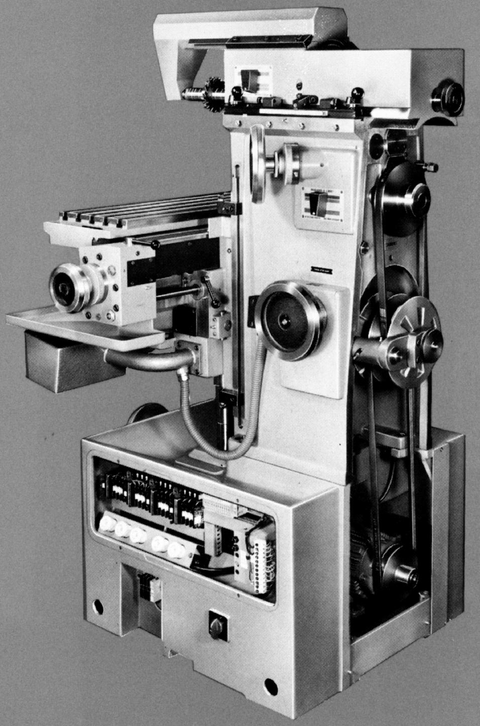
I installed my conversion mill in the workshop last week. An Aciera F4
Some numbers:
Screw Pitch ... 4mm
X backlash (center-nominal) ... 0,23mm == 0.009"
Y backlash (nominal) ... 0.21mm == 0.0083"
Ram droop (Y geometry tolerance) ... 7 microns
Column straightness (Z tolerance) ... 5 microns
Longitudinal parallelism (X tolerance) ... 11 microns
I'm currently preparing the machine to have the ways scraped, and then install one-shot lube.
It looks like I'll be using 300W BLDC Servos with 2:1 belting. I'm still researching the peizo stacks. I've used them on interferometers, but that was a completely different application.

Cheers
Thread is still in the wrong forum
_jC
.
Please Log in or Create an account to join the conversation.
- 1:1
- Offline
- Senior Member
-

- Posts: 67
- Thank you received: 0
If you are doing coordinated movement - like a circle on an XY stage - one axis will be in backlash while the other will be under maximum velocity, your feed in terms of the velocity of the moving part will have to be zero at that point... The backlashing axis becomes the master pretty much which leads to the problem of the profile asking for maximum velocity but the backlash compensation requiring zero velocity. I imagine there are schemes to deal with this... What are they ?
Or have I fluffed my basics ?
Please Log in or Create an account to join the conversation.