Re:Hardinge CHNC 1 Lathe

More
16 years 8 months ago - 16 years 8 months ago #2138 by BigJohnT
Replied by BigJohnT on topic Re:Hardinge CHNC 1 Lathe
Kirk,

I didn't read it with enough light or glasses on LOL, yes it is LM324N.

From reading the data sheet it looks like the output is 28 volts? If that is correct then I can use the output's directly to my 7i37 inputs?

I'm trying as best as I can to gather my info before I place an order with Digikey.

Do you have a part number for a newer equivalent hall switch?

Thanks so much for your help.

John
Last edit: 16 years 8 months ago by BigJohnT.

Please Log in or Create an account to join the conversation.

More
16 years 8 months ago #2144 by Kirk_Wallace
I think the 613SS4 max is 20 Volts, and if the Tantalum capacitor is rated 24 Volts, usually the circuit is run way under the maximum in order to have a safety margin. I would guess your encoder board is meant to run with 12 Volts.

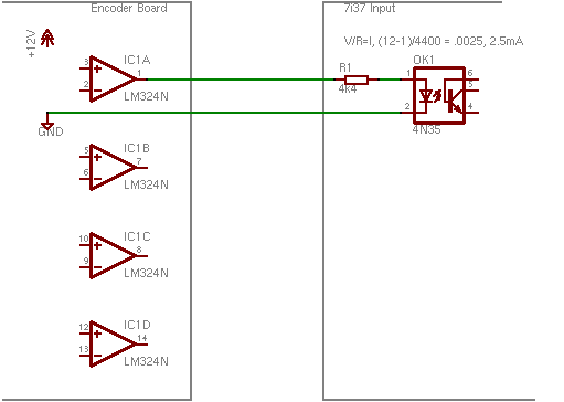
The 7i37 looks like it will take up to 24 Volts. You should check with Peter (from Mesa) to make sure but I think the inputs are just like a 4.4k Ohm resistor and an LED in series. Sorta like this:

(Click on image for lager version)

You need two wires for each encoder output. One to supply the signal, another to complete the circuit to the encoder board's ground.

I would think that you could do a lot of testing before ordering parts. It may be the burnt capacitor is the only bad part. I'll need to do a little more research to find an equivalent for the 613SS4.
--
Kirk Wallace
www.wallacecompany.com/machine_shop/
www.wallacecompany.com/E45/index.html
California, USA

Please Log in or Create an account to join the conversation.
More
16 years 7 months ago - 16 years 7 months ago #2158 by BigJohnT
Replied by BigJohnT on topic Re:Hardinge CHNC 1 Lathe
While pondering what parts to order for the turret I moved on to the spindle. I can get it to go forward with M4 and backward with M3. The output of the 7i33 is reversed of what I'd expect. AOUT2 is -v for M3 and +v for M4. If I reverse the wires then both M3 and M4 go backwards. If I invert IO Pin 019 (P2-39): PWMGen #2, pin Out0 (PWM or Up) (Output) it runs at about 4 times as fast as commaned. If I invert IO Pin 020 (P2-39): PWMGen #2, pin Out1 (PWM or Up) (Output) nothing changes. The drive is a Fanuc digital AC spindle servo drive A06B-6055-H106 if that helps.

I got it fingered out I had to reverse the scale to get it to turn the right way. I'll see if I can make some kind of diagram on this...

Thanks
John
Last edit: 16 years 7 months ago by BigJohnT. Reason: don't know which drive is which I guess

Please Log in or Create an account to join the conversation.

More
16 years 7 months ago #2160 by Kirk_Wallace
I'm glad you got your spindle going. I don't have a clue about that kind of drive.

I looked at your Hall sensor again. Your sensor has two output pins. My guess is that only one is used, but I don't know for sure. Another option would be to make a new board similar to mine. The circuit is much less complicated, but you would need to fabricate a pcb to mount the sensors and wiring on. I can make up a schematic. The electronic parts would be around $15.

Here is Vince's encoder:
www.cnczone.com/forums/showthread.php?t=50685&page=13

I don't think he even uses an encoder chip. I believe the sensors go to a PLC.
--
Kirk Wallace
www.wallacecompany.com/machine_shop/
www.wallacecompany.com/E45/index.html
California, USA

Please Log in or Create an account to join the conversation.

More
16 years 7 months ago #2170 by BigJohnT
Replied by BigJohnT on topic Re:Hardinge CHNC 1 Lathe
Kirk,

I think what I'll do at this point is to replace the blown up cap and go from there and see what the output voltage is and if anything else is blown. I have quite a few things left to sort out while I work on the turret encoder.

Again thanks so much for your help.
John

Please Log in or Create an account to join the conversation.

More
16 years 7 months ago #2176 by BigJohnT
Replied by BigJohnT on topic Re:Hardinge CHNC 1 Lathe
I'm making progress finally YEA! Thanks to all the guys who are helping me out on this project.

Last night I got the axis drive connected and even homed the Z axis. I can see now that the homing section of the manual needs a bit more information.

I'm waiting on the belt for the X to arrive so I can change that out and start tuning the PID.

The default P settings in the HostMot2 sample should NOT be used LOL. P=100 is way too big.

I had some tips somewhere on tuning but can't access it right now :( due to a DOA mobo.

Thanks
John

Please Log in or Create an account to join the conversation.

Time to create page: 0.354 seconds
Powered by Kunena Forum
