Fanuc servo drive integration
- clkeck1
- Offline
- Premium Member
-

Less
More
- Posts: 108
- Thank you received: 2
27 Aug 2012 18:00 #23695
by clkeck1
Replied by clkeck1 on topic Re:Fanuc servo drive integration
I took the path that i was more comfortable with and got a set of 6050 drives for the servos i was using. With some minor rewiring i was able to make this function.
The 6058 drive is 200V and not 185V like the 6057 and 6050. The 20s is the only S series motor that is compatible with both the 185 and 200 volt drives. I don't have the manual with me to tell you what drive you need but i will look tonight.
If you do go this way then you will also need a transformer for 185V and 18V. from your source power
Thanks
Cory
Please Log in or Create an account to join the conversation.
- clkeck1
- Offline
- Premium Member
-
Less
More
- Posts: 108
- Thank you received: 2
30 Aug 2012 02:50 #23759
by clkeck1
Replied by clkeck1 on topic Re:Fanuc servo drive integration
Sorry for the delay.
You would need an A06B-6050-H104 drive with a Rev E or later top board.
Cory
You would need an A06B-6050-H104 drive with a Rev E or later top board.
Cory
Please Log in or Create an account to join the conversation.
- sivaraj
- Offline
- Senior Member
-

Less
More
- Posts: 48
- Thank you received: 23
31 Aug 2012 01:04 - 31 Aug 2012 01:23 #23785
by sivaraj
Replied by sivaraj on topic Re:Fanuc servo drive integration
PWMA / PWMB ,PWMC/PWMD,PWME/PWMF are Three phase sinusoidal PWM
IR /GDR , - R-Phase motor current
IS/GDS - S-Phase motor current
This Fanuc amplifier a three phase bridge with motor phase current feedback will block the PWM if any fault with power section like over current/under voltage
It should be easy to implement with Mesa
Hope this helps
Sivaraj
IR /GDR , - R-Phase motor current
IS/GDS - S-Phase motor current
This Fanuc amplifier a three phase bridge with motor phase current feedback will block the PWM if any fault with power section like over current/under voltage
It should be easy to implement with Mesa
Hope this helps
Sivaraj
Last edit: 31 Aug 2012 01:23 by sivaraj. Reason: mail was not complete
Please Log in or Create an account to join the conversation.
- gr0kr
- Offline
- New Member
-

Less
More
- Posts: 2
- Thank you received: 0
31 Aug 2012 16:48 #23805
by gr0kr
Replied by gr0kr on topic Re:Fanuc servo drive integration
Thanks Sivaraj!
sivaraj wrote:
What is the relationship between PWM A & B (same with C/D, E/F)? Are they the High/Low control lines for half-bridges?
Any idea on the protocol for accessing the Alarm codes (ALM1,2,4,8)?
sivaraj wrote:
PWMA / PWMB ,PWMC/PWMD,PWME/PWMF are Three phase sinusoidal PWM
What is the relationship between PWM A & B (same with C/D, E/F)? Are they the High/Low control lines for half-bridges?
Any idea on the protocol for accessing the Alarm codes (ALM1,2,4,8)?
Please Log in or Create an account to join the conversation.
- PCW
-

- Away
- Moderator
-

Less
More
- Posts: 18979
- Thank you received: 5239
31 Aug 2012 17:05 - 31 Aug 2012 17:06 #23807
by PCW
Replied by PCW on topic Re:Fanuc servo drive integration
The alarm bits are just a 4 bit code(codes are listed in one of the controller manuals), This would require tri-stateable differential drivers on those PWM pins (and knowing when to change dir: DRDY?)
Last edit: 31 Aug 2012 17:06 by PCW.
Please Log in or Create an account to join the conversation.
- sivaraj
- Offline
- Senior Member
-
Less
More
- Posts: 48
- Thank you received: 23
01 Sep 2012 00:21 #23816
by sivaraj
Replied by sivaraj on topic Re:Fanuc servo drive integration
Yes 6-PWMs signals for 6 transistors on the 3phase bridge.
I worked on this about a year back .So If I remember right,the alarm signals are just multiplexed digital signals.No other protocal involved.
I worked on this about a year back .So If I remember right,the alarm signals are just multiplexed digital signals.No other protocal involved.
Please Log in or Create an account to join the conversation.
- MANOLOMARAVILLAS
-
- Offline
- New Member
-
Less
More
- Posts: 6
- Thank you received: 0
03 Nov 2015 02:01 #64632
by MANOLOMARAVILLAS
Replied by MANOLOMARAVILLAS on topic Fanuc servo drive integration
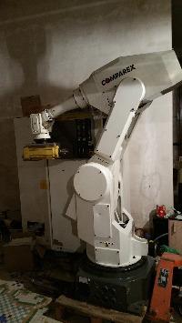
hello i am again. s700 have a Fanuc robot, buy blcd picosystem converters. I also have these drivers.
and according to my research are these,,,,,
I share all my data,
image valid for::
a06b-6058-h221
a06b-6058-h222
a06b-6058-h012
a06b-6058-h006
and according to my research are these,,,,,
I share all my data,
image valid for::
a06b-6058-h221
a06b-6058-h222
a06b-6058-h012
a06b-6058-h006
Please Log in or Create an account to join the conversation.
- MANOLOMARAVILLAS
-
- Offline
- New Member
-
Less
More
- Posts: 6
- Thank you received: 0
03 Nov 2015 02:07 #64636
by MANOLOMARAVILLAS
Replied by MANOLOMARAVILLAS on topic Fanuc servo drive integration
pwm a .....pwmf is pwm control 6 trifasic mosfets...
drdy- servo ready
mcon:mcc , activated relay power 200va in mosfets control.(voltaje power start )
ir and is,,,,,, sending to control amp power windings motor....
drdy- servo ready
mcon:mcc , activated relay power 200va in mosfets control.(voltaje power start )
ir and is,,,,,, sending to control amp power windings motor....
Please Log in or Create an account to join the conversation.
- andypugh
-

- Offline
- Moderator
-
Less
More
- Posts: 23415
- Thank you received: 4976
03 Nov 2015 02:17 #64638
by andypugh
Replied by andypugh on topic Fanuc servo drive integration
Welcome to the forum.
Are you adding information to this thread (Which is rather old) for future reference? In that case, thank you.
Or, do you have some questions?
Are you adding information to this thread (Which is rather old) for future reference? In that case, thank you.
Or, do you have some questions?
Please Log in or Create an account to join the conversation.
- jmelson
- Offline
- Moderator
-
Less
More
- Posts: 825
- Thank you received: 159
03 Nov 2015 10:11 #64656
by jmelson
Replied by jmelson on topic Fanuc servo drive integration
These Fanuc servo amplifiers require SIX PWM signals for each axis. If you have 5 motors on the robot (typical) then you would need THIRTY fast PWM channels to drive the 5 axes. Also, the top and bottom transistor of each pair must never be on at the same time, or it will likely blow the transistors. It might be better to just use 3 PWM generators with a pair of deadtime generators each to produce the 6 transistor drive signals. This would get into custom FPGA development.
Jon
Jon
Please Log in or Create an account to join the conversation.
Time to create page: 0.105 seconds