Input Wiring Yaskawa Servopack for Miyano lathe
- djs14
- Offline
- Senior Member
-

Less
More
- Posts: 56
- Thank you received: 0
24 Dec 2015 22:50 #67304
by djs14
Input Wiring Yaskawa Servopack for Miyano lathe was created by djs14
Hello all,
First post with you guys. I want to retro my old Miyano lathe to LinuxCNC.
The machine has been sitting for years. My first goal is to just jog the motors on each axis by applying voltage to the appropriate pins on the drives. I have some documentation and have been searching on the web and this site but cannot seem to find any info for the Yaskawa CPCR MR052 drives with two 20 pin connectors. There's plenty of info for drives with only one 20 pin connector. I found some documentation for a drive with two 20 pin connectors but the pin definitions did not seem to make sense with what I'm seeing on these drives.
There was another gent on here looking for the same info. In his thread he commented that he made the motors move when applying voltage to the pins on the far left but a relay or something dropped out. I can't get this to correlate to any schematics I've looked at.
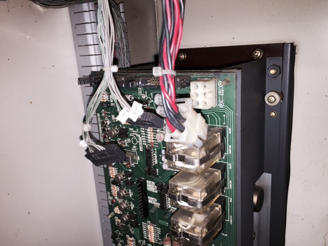
Here's some more info about each of the connectors:
"Left" connector - 1CN
7 wires total, 4 of which make up two twisted pairs (2 grn, 2 gry). I traced these two back to 20 pin "F" connector on what I believe is the ECU board in the front panel. The other 3 gry wires ? The twisted pair at the far left I believe is where the other poster applied voltage and got the axis to move.
"Right" connector - 2CN
10 wires total, 2 of which are a twisted pair that I could not trace to the ECU, so maybe this pair goes to the motor tach, which I can trace.
The remaining 8 wires are gray.
I think the limit switches are wired into theses connectors also, so that shouldn't be too hard to trace out and looks like it would account for 3 more of the wires.
Appreciate any input or thoughts.
Best to all,
Sean
First post with you guys. I want to retro my old Miyano lathe to LinuxCNC.
The machine has been sitting for years. My first goal is to just jog the motors on each axis by applying voltage to the appropriate pins on the drives. I have some documentation and have been searching on the web and this site but cannot seem to find any info for the Yaskawa CPCR MR052 drives with two 20 pin connectors. There's plenty of info for drives with only one 20 pin connector. I found some documentation for a drive with two 20 pin connectors but the pin definitions did not seem to make sense with what I'm seeing on these drives.
There was another gent on here looking for the same info. In his thread he commented that he made the motors move when applying voltage to the pins on the far left but a relay or something dropped out. I can't get this to correlate to any schematics I've looked at.
Here's some more info about each of the connectors:
"Left" connector - 1CN
7 wires total, 4 of which make up two twisted pairs (2 grn, 2 gry). I traced these two back to 20 pin "F" connector on what I believe is the ECU board in the front panel. The other 3 gry wires ? The twisted pair at the far left I believe is where the other poster applied voltage and got the axis to move.
"Right" connector - 2CN
10 wires total, 2 of which are a twisted pair that I could not trace to the ECU, so maybe this pair goes to the motor tach, which I can trace.
The remaining 8 wires are gray.
I think the limit switches are wired into theses connectors also, so that shouldn't be too hard to trace out and looks like it would account for 3 more of the wires.
Appreciate any input or thoughts.
Best to all,
Sean
Please Log in or Create an account to join the conversation.
- andypugh
-

- Offline
- Moderator
-

Less
More
- Posts: 19875
- Thank you received: 4642
24 Dec 2015 23:39 #67306
by andypugh
Replied by andypugh on topic Input Wiring Yaskawa Servopack for Miyano lathe
Are the connectors both fully populated? Do they all go to different pins on the PCB?
I am wondering if the pinouts are identical and redundant, to allow easier separation of command and feedback wiring.
I am wondering if the pinouts are identical and redundant, to allow easier separation of command and feedback wiring.
Please Log in or Create an account to join the conversation.
- djs14
- Offline
- Senior Member
-
Less
More
- Posts: 56
- Thank you received: 0
24 Dec 2015 23:51 #67307
by djs14
Replied by djs14 on topic Input Wiring Yaskawa Servopack for Miyano lathe
No. 7 wires in one plug, 10 wires in the other, and they are 20 pin plugs.
They are the same for each axis ... as in both drives have both of these plugs.
Cheers
They are the same for each axis ... as in both drives have both of these plugs.
Cheers
Please Log in or Create an account to join the conversation.
- andypugh
-
- Offline
- Moderator
-
Less
More
- Posts: 19875
- Thank you received: 4642
24 Dec 2015 23:53 #67308
by andypugh
But is there any overlap in populated pins between the plugs?
ie, is it possible that each pin has the function allocated to that position in the single 20 pin plug?
Replied by andypugh on topic Input Wiring Yaskawa Servopack for Miyano lathe
]7 wires in one plug, 10 wires in the other, and they are 20 pin plugs.
But is there any overlap in populated pins between the plugs?
ie, is it possible that each pin has the function allocated to that position in the single 20 pin plug?
Please Log in or Create an account to join the conversation.
- djs14
- Offline
- Senior Member
-
Less
More
- Posts: 56
- Thank you received: 0
27 Dec 2015 00:07 #67355
by djs14
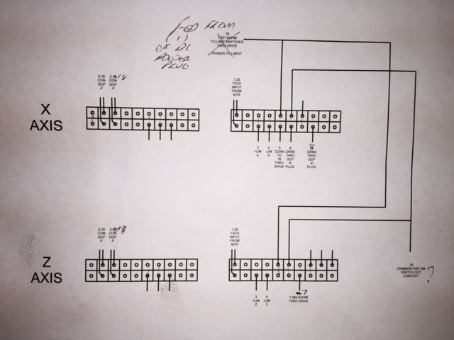
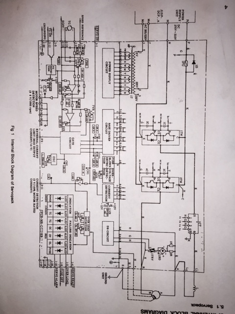
Ok that was a good thought but still doesn't seem to make any sense. I've attached a few pics. One of them is a cad drawing I made of the plugs to try and make sense of multi-meter readings to various schematics. I actually have a machine schematic also which I will post to see if there's something in there that makes sense of all this. Unfortunately the manual with this machine schematic is for a yasnac 2000b control but it has a different CPU than my machine, so a lot of the wiring schematics are useless. I was hoping the drives would make sense but they're not... same problem as other gent that posted with 2 x 20 pin input plugs.
Thanks for any help or suggestions!
Replied by djs14 on topic Input Wiring Yaskawa Servopack for Miyano lathe
]7 wires in one plug, 10 wires in the other, and they are 20 pin plugs.
But is there any overlap in populated pins between the plugs?
ie, is it possible that each pin has the function allocated to that position in the single 20 pin plug?
Ok that was a good thought but still doesn't seem to make any sense. I've attached a few pics. One of them is a cad drawing I made of the plugs to try and make sense of multi-meter readings to various schematics. I actually have a machine schematic also which I will post to see if there's something in there that makes sense of all this. Unfortunately the manual with this machine schematic is for a yasnac 2000b control but it has a different CPU than my machine, so a lot of the wiring schematics are useless. I was hoping the drives would make sense but they're not... same problem as other gent that posted with 2 x 20 pin input plugs.
Thanks for any help or suggestions!
Please Log in or Create an account to join the conversation.
- djs14
- Offline
- Senior Member
-
Less
More
- Posts: 56
- Thank you received: 0
27 Dec 2015 00:18 #67356
by djs14
Replied by djs14 on topic Input Wiring Yaskawa Servopack for Miyano lathe
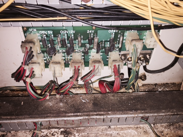
I did not see the power plug pictured above on any of the schematics. I was expecting it to trace to the main power supply but I think it goes to this power supply in pic. I have seen no documentation for this one, and it's not obvious where the power goes in. The large gauge wires that are visible are all ground wires. As I mentioned in first post I wanted to power up the drives. I was hoping I could just use a stand alone power supply for any DC voltage the drive needed. It's a bummer my machine schematics aren't better, but they did show the limit switches wired into the drive that no other diagrams were showing. I will take a pic and post that.
Oh and I also noticed the input plugs were not identical in wiring for X and Z drives. This can be seen on the plug schematic I posted on previous post. Sorry my post is rambling ... just trying to get some thoughts clarified to figure out what to do next.
Oh and I also noticed the input plugs were not identical in wiring for X and Z drives. This can be seen on the plug schematic I posted on previous post. Sorry my post is rambling ... just trying to get some thoughts clarified to figure out what to do next.
Please Log in or Create an account to join the conversation.
Time to create page: 0.637 seconds